Clocks, alarms and time gadgets are the most common devices that you will find in any typical household, dorm, apartment, workstation and any room you might walk into. However basic and conventional watch designs can at times be blunt, out of style or do not represent the energy of the room. Making a unique homemade clock may be an intriguing project for most engineers, enthusiasts, and students. To complete this project, an Arduino microcontroller with a few fully customizable components may be utilized. In this post, we'll use Arduino to build a working clock with built-in alarm functionality.
Arduino microcontrollers have become vastly utilized by students, hobbyists and event engineers for prototyping purposes. Majorly, this can be attributed to their low cost and simplicity to deal with, making them the perfect microcontroller for small DIY projects. There are about a million projects that you can try out in your dorm room or apartment for under 100 USD. The community surrounding the Arduino development is also very friendly and helpful making it the perfect tool for beginners and those who wish to mess around with electronics.
The components, knowledge and skill level required for this project are both inexpensive and very basic.
What is the purpose of this project?
This project tries to combine the hardware and software ideas of Arduino to build a straightforward alarm clock with a 4-digit 7-segment display. You will get vital skills and experience working with Arduino boards and displays by completing this project, as well as a handy tool that you may use in your daily life.
You may personalize a clock with an alarm by making one yourself per your tastes and requirements. To fit your individual needs, you may change the display's format, brightness, and alarm settings. Additionally, you may develop and investigate additional projects in the future because this project acts as a building block for more intricate time-based applications.
Arduino Simple Clock with a TM1637 4-digit 7-segment display
This project is meant to be simple and easy. There are two variants of the 4-digit 7-segment display, the TM1637 the traditional 4-digit 7-segment display. Both can be used to program a clock, temperature display and so forth. However, when using them there are subtle differences, the bare 4-digit 7-segment display requires 12 connection pins whereas the TM1637 has an IC that is preprogrammed to map the segments and thus reducing the pins to just four pins.
For the simplicity of this tutorial and beginners, we will learn how to control a TM1637 4-digit 7-segment display with Arduino and use it to create a digital clock with an alarm.
What you will need
Depending on the display variation that you choose to use, the wiring and code will alter significantly. If you choose to use a TM1637 4-digit 7-segment display rather than a conventional 7-segment display you can use this article as a guide. On the other hand, if you choose the conventional 4-digit 7-segment display, you can check out our guide on that.
Here is a list of the requirement that you will need for this project:
Hardware
4-digit, 7-segment display on the TM1637
As stated earlier there the difference between the conventional 4-digit 7-segment display and the TM1637 is rather apparent physically in the number of pins. It is also worth noting that the programming for the TM1637 is rather simpler.

Figure 1: TM1637 IC module Display
The 4-digit 7-segment display has 7 or sometimes 8 addressable LEDs that can be controlled individually. In the figure below they are labelled A to G, and sometimes there might be a separator LED making a total of 8. In the conventional display, the programmer has to individually address all the segments and control them individually. With the TM1637 IC, the segments are pre-mapped into a library and thus it is easier to code.

Figure 2: The segments of a 7 Segment Digit
A TM1637 IC is used in a wide variety of display modules that you can purchase. Different combinations of colour, size, dots, and connection points are possible.
Arduino board
There are very many microcontroller boards in the market including banana pi, raspberry pi, Arduino, Genuino and so many others. For this project, however, we will be using Arduino. Any Arduino board, including the Uno, Nano, and Mega models.
Most preferred is the Arduino Mega for its generosity in pins, but since we are using a 4-pin TM1637, Arduino Uno will also be a good and cheaper choice.
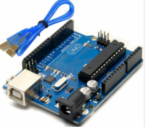
Figure 3: Arduino Uno
Jumper wires are small connector cables that are used to like between devices and vary shapes, sizes and types of connectors. They have a wide array of applications but in this case, will be used to link the TM1637 display module to the Arduino board.
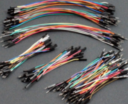
Since we have more than one item being controlled by the Arduino board and also receiving power, it would also be prudent to use a breadboard for ease and manageability.
Alarm Speaker
There are several methods for producing an audible alert that you can use to accomplish the alarm functionality in this project. Here are a few typical techniques:
Buzzer
To produce sound, you can use either an active buzzer or a passive buzzer. Passive buzzers need an oscillating signal from the Arduino to produce sound, but active buzzers make noise when voltage is applied. Connect the buzzer to a digital Arduino pin.
Piezo speaker
Different tones and sounds can be produced using a piezo speaker. When voltage is supplied, it acts as an element that produces sound. Connect the piezo speaker's positive and negative terminals to the ground and an Arduino digital pin, respectively. To create the desired frequency and duration for the alarm sound, use the tone () method.

Figure 5: Piezo Sounder
Power supply
The Arduino board requires a power supply. Depending on the Arduino board you are using, either a USB cable linked to your computer or a separate power supply can be used for this.
USB cable
To program and power the Arduino board from your computer, a USB cable is needed.
For connections and assembly, simple tools like a screwdriver, wire cutter/stripper, and pliers may be used.
Software
In terms of software, there is not much that is necessary for this project as we are not doing simulations since it is just a simple project.
Computer with Arduino IDE
To write and upload the Arduino code, you will need a computer. From the official Arduino website, install the Arduino IDE (Integrated Development Environment). The Arduino IDE is a simple-to-use interface and comes with all the prepackaged libraries and drivers for all Arduino models.
Getting started
Before getting started with the coding part, we must first wire up our display and the alarm. In this case, we are using four pins for the TM1637 and two pins for the piezo speaker that will act as our sounder. Here is what the wiring should look like:
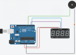
Figure 6: The Wiring for the Setup
Wiring
The following procedures should be followed to begin wiring the TM1637 4-digit 7-segment display:
- Connect the TM1637 display module's VCC to the Arduino board's 5V pin.
- Connect the TM1637 display module's GND to the Arduino board's GND pin.
- Connect the TM1637 display module's CLK to a digital Arduino board pin, such as Pin 2.
- Connect the TM1637 display module's DIO to a different digital Arduino board pin, such as Pin 3.
The following steps should be followed to wire the piezo speaker for alarm functionality:
- Connect the piezo speaker's positive ( ) connection to a digital pin (such as Pin 6) on the Arduino board.
- Connect a current-limiting resistor (about 100 ohms) to the piezo speaker's negative terminal (-).
- The GND (ground) pin on the Arduino board should receive the resistor's other end.
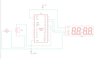
Figure 7: Schematic Diagram for the Wiring
Programming
This project as stated is to control a display, a 4-digit 7-segment display, to display a working clock and also provide an alarm functionality using a buzzer or piezo sounder. The following code can be used to achieve that.
Prerequisite
Before moving forward with the code, you will need to make sure that you have installed in your Arduino IDE the ‘TM1637Display’ and ‘toneAC’ libraries. These will enable you to simplify your code and also address the LEDs in the TM1637 module.
If you have not installed them here is a simple guide to do it:
- Go to “Sketch”, then “Include Library” and “Manage Libraries”
- Then search for the two libraries, if you have them installed you can proceed.
- Else you will need to install them and restart your IDE.
And you are good to go.
Code
A brief of the code:
- Specify any required libraries: The code includes the toneAC library for producing tones with the piezo speaker and the TM1637Display library for managing the TM1637 display.
- Define pin assignments: The connections between the Arduino board and the TM1637 display are described by the CLK_PIN and DIO_PIN constants. For the connection to the piezo speaker, the ALARM_PIN constant is defined.
- Create a new instance of the TM1637Display class, and initialize the variables for the current time (hour, minute, and second), as well as the alarm time (alarmHour, alarmMinute).
- The display's brightness is set, and the ALARM_PIN is defined as an output pin, in the setup function.
- Loop Function: The loop function contains the majority of the program's logic. It checks to see if the alarm needs to be set while updating the time and showing it on the TM1637 display.
- Update time: The updateTime function is in charge of handling rollover situations and incrementing the time variables (hour, minute, and second).
- Display time: To display the time on the display, the displayTime function turns the time variables into an array of digit values using the TM1637Display library. It also has a one-second delay to allow for seamless updating.
- Trigger alarm: The triggerAlarm function produces a 2000Hz tone on the ALARM_PIN for 1 second to signal the alarm. It does this by utilizing the toneAC library. The alarm status is then checked once more after a one-second delay.

Figure 8: Code for the Arduino Program
It is important to note that you need to customize the code before uploading it to your device. This includes using your local time, at the time of upload and also setting the preferred alarm time and also the frequency of ringing. The presets in this code can be adjusted to suit all the user needs. The code is also designed with configurability in mind.
It is also possible to have more than one alarm set. It can be achieved by setting more than one alarmhour variable. The piezo speaker attached to ALARM_PIN will emit a 1-second tone when the alarm time (determined by alarmHour and alarmMinute) is reached.
Uploading the code
This is the easiest step, in the entire project.
- Upload the code to the Arduino board. First, after the wiring is done, confirm all the pins are tight and connect the USB to the Arduino board and the other end to the computer.
Use the verify and upload button on the IDE
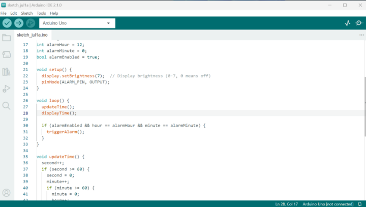
Figure 9: Arduino IDE
- Observe the behaviour of the 4-digit 7-segment display as well as the sounder at the time of the alarm. it should start displaying the time on the TM1637 4-digit 7-segment display. The alarm should also produce a 1-second tone at the time of the alarm.
- Troubleshoot any issues such as incorrect wiring, component failures, or incorrect code logic. If there are any errors they can be addressed on the IDE, and you can utilize the debugger to understand any errors better.
- If the program goes as needed, you can adjust and customize it as needed to add more features or modify the alarm behaviour according to your requirements.
Conclusion
In conclusion, this project entails building a straightforward clock with an alarm utilizing a piezo speaker and a 4-digit 7-segment display from TM1637. You may program an Arduino board to display the clock in real-time and sound an alarm at a predetermined period.
The project offers a practical introduction to Arduino hardware and programming. It enables you to examine the TM1637 display's features and incorporate an audio alarm utilizing the piezo speaker.


