What is a clamper circuit?
In electronics, the clamper or clamper circuits are used to add a DC level to an AC signal. By using the clamper circuits we can place the positive and negative peaks of the signals at the desired levels. Due to the phenomenon of DC level shifting, the clamper circuit is called a Level Shifter. A simple Clamper circuit is composed of an energy storage device e.g. capacitor (C), a resistor (RL), a diode, and a DC voltage battery if required.
Working principle of clamper circuit:
A clamper circuit subtracts or adds a DC component to the input signal. If a positive DC component is added to the input signal input is pushed toward the positive side on the other hand in the case of a negative DC component it is pushed toward the negative side. So we can identify two types of clamper by this phenomenon positive clamper and negative clamper if the clamper circuit shifts the input signal in the upward direction it is said to be a positive clamper circuit as shown in the picture below.
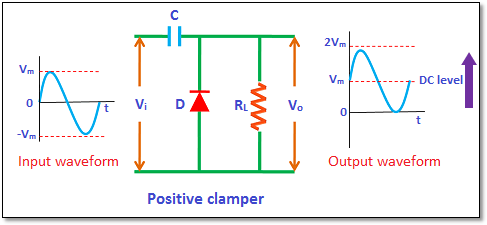
Figure 1 positive clamper circuit diagram
Similarly, if the clamper circuit shifts the input signal in the downward direction it will be a negative clamper circuit as shown in the picture below.
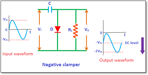
Figure 2 negative clamper circuit diagram
Types of Clampers:
Based on DC-level shifting properties the clamper circuits are classified into three types
- Positive Clamper
- Negative Clamper
- Biased Clamper
- Positive Clamper:
The positive clamper consists of an input voltage source(Vi), connected with a capacitor(C), Load resistor (RL), and a diode (D). The output voltage source is connected parallel with the diode as shown in the figure above for positive clamper. The positive clamper blocks the input signal when the diode is forward-biased and transfers the input signal to the output voltage source only when the diode is reverse-biased. The diode connected parallel with the voltage output source is forward biased during the negative half cycle of an AC input signal so no output signal passes through the diode. This current is utilized in charging the capacitor to its peak value Vm.
During the negative cycle of AC input voltage, the diode is reverse biased and the signal appears at the output voltage because no current will flow in the diode when it is reverse biased. The input AC voltage signal adds up with the voltage stored in the capacitor and appears as the output voltage (i.e. VO= Vm Vm =2 Vm ) and we get an upward-shifted output signal.
- Negative Clamper
The diode is forward-biased during the positive half cycle of the input AC signal so no signal appears at the output end. The diode will allow current to flow through it in the forward-biased condition that will charge the capacitor to its maximum value with inverse polarity (-Vm ). During the negative cycle when the diode is reverse biased, no current flows through the diode therefore at the output end voltage appears as the sum of input voltage and voltage stored in the capacitor (i.e. VO= Vm Vm =2 Vm).
- Biased Clampers:
Biased Clampers working is similar to positive and negative clampers only difference is the addition of a DC Voltage battery in the circuit. These Clampers are used when an additional shift of the DC level is required. These are of four types
- Positive clamper with positive bias
- Positive clamper with negative bias
- Negative clamper with positive bias
- Negative clamper with negative bias
Positive clamper with positive bias:
The battery voltage forward biases the diode during the positive half cycle when the battery voltage is higher than the input supply voltage so the current flowing through the diode charges the capacitor When we supply the input AC voltage signal then it makes the diode reverse biased and current doesn’t flow through it.
The diode is forward biased during the negative half cycle that allows current flow through the diode and charge the capacitor.
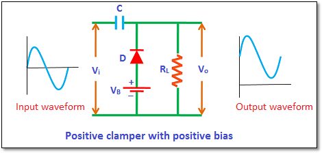
Figure 3 positive clamper with positive biased circuit
Positive clamper with negative bias:
In case of a negative half cycle of the battery voltage reverse biases the diode. When the battery voltage is high as compared to the input voltage it causes a transfer of signal at the output end. When we supply the input voltage it will be greater than the battery voltage so the diode will be forward biased and current will flow through it and charge the capacitor. During the positive half cycle due to the input AC voltage signal and battery voltage, the diode will be forward-biased and a signal will appear at the output end. This output voltage will be the sum of stored capacitor voltage and input voltage.
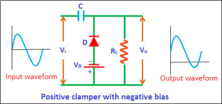
Figure 4 positive clamper with negative biased circuit
Negative clamper with positive bias:
The diode is reversed biased by battery voltage during the positive half cycle of the input signal. On the other hand, when the input voltage is greater than the battery voltage after supplying it was forward biased the diode. So current will flow through the diode and charge the capacitor. The diode will be reversed in the negative half cycle, and a signal sum of supply voltage and battery voltage appears at the output end.
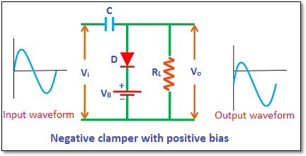
Figure 5 negative clamper with positive biased circuit
Negative clamper with negative bias:
The battery voltage and input AC voltage will forward bias the diode during the positive half cycle, and the current flowing through the diode will charge the capacitor. And the diode will be forward bias in the negative half cycle, due to battery voltage. After supplying the input signal higher input voltage as compared to the battery voltage revere bias the diode and as a result, a signal appears at the output end.
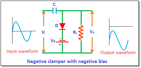
Figure 6 negative clamper with negative biased circuit
Applications of clamper circuit:
- Clampers can be used as DC restorers.
- Clampers can be used as voltage doublersand also play a vital role in eliminating distortions
- Clampers can be used for the protection of electronic components e.g. amplifiers
- Clampers help us identify the polarity of electronic circuits.
Here is related video to help you understand more.