What is an H-Bridge
The H-bridge is a relatively simple circuit that typically consists of four independently controlled switch components (such as MOSFETs), arranged in an H-shape. The H-bridge circuit allows for the switching of the polarity of an attached load. The most common application of an H-bridge is to drive a DC motor, enabling direction control. The specific circuit diagram is shown below:
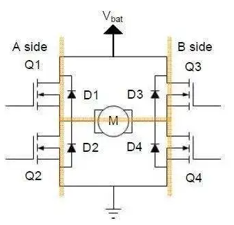
H-bridge circuit
As shown in the diagram, the switch components (Q1-Q4) are typically bipolar transistors or FET transistors, and in some high-voltage applications, IGBTs are used. The diodes (D1-D4) are called clamp diodes and are usually Schottky diodes. The top of the bridge is connected to the power source (battery), and the bottom is grounded. Although there are some limitations, typically the four switch components can be independently turned on and off.
ALSO READ: HOW TO TEST FOR A FAULTY DIODE IN A CIRCUIT
How does an H-bridge work
The working principle of an H-bridge circuit mainly involves the control of the switch components to achieve different voltage loadings and flow of current. In an H-bridge circuit, typically two switch components are activated while the other two are deactivated, ensuring that there are always two switch components connected to the power source while the other two are disconnected.
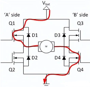
If Q1 and Q4 are conducting, the left lead of the motor will be connected to the power source, while the right lead will be grounded. Current will start flowing through the motor, resulting in forward current flow, and the motor shaft will begin rotating.
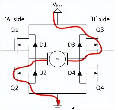
If Q2 and Q3 are conducting, reversal will occur. The motor will be energized in the reverse direction, and the shaft will start rotating backward.
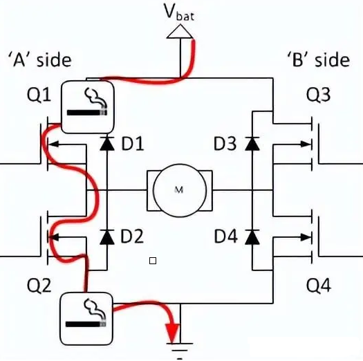
Be careful not to simultaneously conduct Q1 and Q2 (or Q3 and Q4). If they are conducting simultaneously, it will create a very low-impedance path between the power supply and ground, effectively short-circuiting the power supply. This condition is known as "shoot-through" and can potentially damage other components in the circuit.
H-bridge motor driver: Implementing control of the H-bridge
An H-bridge motor driver is a circuit module specifically designed to control DC motors. It is based on the principles of the H-bridge circuit and enables motor control for forward rotation, reverse rotation, and speed control. The H-bridge motor driver typically includes circuit protection features and interface circuits to connect with control signal sources such as Arduino.
Here are the basic steps to implement control of an H-bridge motor driver:
- Select an appropriate H-bridge motor driver: Choose a suitable H-bridge motor driver module based on the required motor current and voltage specifications. Ensure that the selected driver supports the desired current and voltage range.
- Connect the power supply: Connect the power supply to the power input of the H-bridge motor driver. Make sure the voltage of the power supply matches the rated voltage of the motor and the driver, and provide the appropriate current as required.
- Connect the motor: Connect the two terminals of the DC motor to the motor outputs of the H-bridge motor driver. Ensure that the positive and negative terminals of the motor are correctly connected to rotate the motor in the desired direction.
- Connect control signals: Connect the digital pins of the control signal source (such as Arduino) to the control inputs of the H-bridge motor driver. Depending on the specifications and requirements of the driver, connect the control signals to the inputs for forward rotation, reverse rotation, and speed control.
- Connect power and ground: Connect the negative terminal (ground) of the power supply to the ground pin of the Arduino to ensure a common ground reference.
- Write control code: Write the control code using an appropriate programming language (such as C/C for Arduino). Use digital pins or PWM signals, as needed, to control the control inputs of the H-bridge motor driver. Write the code to implement the desired logic for forward rotation, reverse rotation, and speed control.
- Upload and run the code: Upload the written code to the Arduino board and ensure that the board is connected to the computer. Run the code to control the outputs of the H-bridge motor driver, thereby controlling the behavior of the motor.
H-bridge IC: Integrated solution for simplifying H-bridge circuits
An H-bridge IC is an integrated circuit (IC) specifically designed to simplify the construction and control of H-bridge circuits. It integrates various components of the H-bridge circuit, such as switch elements and protection circuits, into a single chip, providing a convenient and user-friendly solution.
The main advantage of an H-bridge IC is that it offers an integrated solution, simplifying complex circuit designs and component selections into a single component. It typically features the following characteristics and functionalities:
Integrated H-bridge circuit: An H-bridge IC integrates all the necessary components of an H-bridge circuit, including switch elements (typically MOSFETs or IGBTs), current sensing circuits, and protection circuits (such as overcurrent and overtemperature protection).
Control interface: H-bridge ICs provide interfaces for controlling the state of the switch elements, typically through logic input pins or serial communication interfaces (such as SPI or I2C).
Internal protection features: H-bridge ICs usually have built-in current limiting and overtemperature protection features to safeguard the circuit and motor from damage.
Power management: H-bridge ICs can offer power management features such as power supply voltage monitoring, current limiting, and low-power modes.
Efficiency and performance optimization: H-bridge ICs are often optimized for high-performance and high-power applications, providing optimal performance and efficiency.
Using an H-bridge IC greatly simplifies the design and construction process of an H-bridge circuit, reduces component count and complexity, and provides a more reliable and integrated solution. With appropriate control signals, it is easy to achieve forward rotation, reverse rotation, and speed control of the H-bridge using an H-bridge IC.
Applications of H-bridge circuits
Robots and unmanned vehicles: H-bridge circuits are commonly used in robots and unmanned vehicles to control the direction and speed of motors. By controlling the H-bridge circuit, actions such as forward movement, backward movement, and steering can be achieved.
Automotive industry: H-bridge circuits find wide applications in the automotive industry for controlling the drive systems of electric vehicles. They can control motor direction, acceleration, and braking in electric cars, providing efficient and reliable drive control.
Industrial automation: H-bridge circuits are extensively used in industrial automation to control motors in various industrial equipment and machinery. They enable motor forward and reverse rotation, speed control, and position control, used in automated production lines, robotic arms, conveyor belts, and other equipment.
Power tools and home appliances: H-bridge circuits are also commonly used in power tools and home appliances. For example, electric drills, lawnmowers, electric fans, and other devices employ H-bridge circuits to control the working state and speed of motors.
Applications requiring position control: H-bridge circuits can be used in conjunction with encoders or position sensors to achieve motor position control. This application is common in devices such as robots, automatic doors, camera gimbals, and other equipment requiring precise position control.
Power conversion and inverters: H-bridge circuits also play a crucial role in power conversion and inverters. They can convert DC power to AC power, used in solar power systems, uninterruptible power supply (UPS) systems, and other fields.
Practical Application Example
Integrating H-bridge, H-bridge driver, and Arduino
One practical application example is controlling a small DC motor using an H-bridge, H-bridge driver, and Arduino. Here are the basic circuit connections and workflow:
Connect the H-bridge driver: Connect the power pins of the H-bridge driver to a power source, ensuring that the voltage matches the driver's rated voltage. Connect the control input pins of the driver to the digital pins of the Arduino.
Connect the H-bridge: Connect the two terminals of the DC motor to the outputs of the H-bridge driver, ensuring that the positive and negative terminals are correctly connected.
Connect power and ground: Connect the negative terminal (ground) of the power source to the ground pin of the Arduino, ensuring a common ground reference.
Write control code: Use the programming language of the Arduino (such as C/C ) to write the control code. Depending on the requirements, use digital pins or PWM signals to control the control input pins of the H-bridge driver. Write the code to implement the desired logic for forward, reverse, and speed control.
Upload and run the code: Upload the written code to the Arduino board and ensure that the board is connected to the computer. Run the code to control the outputs of the H-bridge driver, thus controlling the behavior of the motor.
By controlling the H-bridge driver through Arduino, it is possible to achieve motor forward, reverse, and speed control.
This integrated system allows for precise control of the motor's direction and speed, making it suitable for various applications such as robotics, automation, and prototyping projects.
H-bridge inverter
Another practical application example is using an H-bridge inverter to convert a DC power source into an AC power source. An H-bridge inverter is a special application of an H-bridge circuit used for converting DC power into AC power. While a regular H-bridge circuit is primarily used to control the direction and magnitude of current for DC motors or loads, an H-bridge inverter extends the functionality of the H-bridge circuit to achieve DC to AC conversion. This type of inverter is commonly used in applications such as solar power systems and uninterruptible power supply (UPS) systems.
Here are the basic circuit connections and workflow:
Connect the H-bridge inverter: Connect the DC input pins of the H-bridge inverter to the DC power source, ensuring that the voltage matches the rated voltage of the inverter. Connect the AC output pins of the inverter to the load (such as household appliances or other AC devices).
Control logic and protection: Set up the control logic and protection features of the inverter according to its specifications and requirements. This may involve setting parameters such as the inverter frequency, output voltage, and overload protection.
Connect power and ground: Connect the negative terminal (ground) of the power source to the ground pin of the inverter, ensuring a common ground reference.
Upload and run code (if applicable): Some inverters may require specific control code or configuration files to set their operating parameters. In such cases, upload the appropriate code or configuration file to the inverter and ensure it is connected to the control device.
By using an H-bridge inverter, it is possible to convert DC power into AC power, enabling the usage of AC devices or powering AC systems. The specific control logic and configuration can be adjusted based on the requirements of the application.
ALSO READ: Three Phase Inverter - 120 Degree Conduction Mode
Advantages of H-bridge circuits
Direction control: H-bridge circuits can achieve motor forward and reverse rotation, allowing them to adapt to different application requirements.
Speed control: By adjusting the state and duty cycle of the switching elements in the H-bridge circuit, motor speed control can be achieved, providing more flexible motion control.
High efficiency: H-bridge circuits typically use high-efficiency switching elements such as MOSFETs or IGBTs, which have low conduction and switching losses, thus improving the overall system efficiency.
Power handling capability: Due to the ability of the switching elements in the H-bridge circuit to share the current load, it can handle higher power applications, making it suitable for driving high-power motors or loads.
Regenerative braking: When the motor decelerates or brakes, the generated back electromotive force (EMF) can be recovered and utilized through the H-bridge circuit, thereby improving energy efficiency.
Overall, H-bridge circuits provide versatile control capabilities, efficient power handling, and the ability to handle bidirectional motor control, making them essential components in various applications, including robotics, automation, electric vehicles, and power conversion systems.
Considerations for H-bridge circuits
- Protection circuitry: Due to the involvement of high power and high currents, appropriate protection measures such as overcurrent protection, overtemperature protection, and short-circuit protection must be implemented to ensure the safe operation of the circuit and motor.
- Power capacity: The power supply system should have sufficient capacity to meet the power demands of the motor during startup, acceleration, and load variations, and to prevent power supply overload.
- Isolation and insulation: In certain applications, isolation and insulation techniques may be required to ensure electrical isolation between the motor and control circuitry, improving safety and reducing interference.
- Control signals: The logic signals controlling the H-bridge circuit must be properly matched with the drive circuits of the switching elements to avoid overvoltage or overcurrent situations.
- Temperature management: The switching elements in an H-bridge circuit generate heat, and heat dissipation and temperature management must be considered in the design to ensure that the components operate within a safe temperature range.
FAQS
1. How to make an H-bridge
To make an H-bridge, you will need four power switches (such as transistors or MOSFETs) and a control circuit. Connect the switches in a bridge configuration, with the load (such as a motor) connected between the switches. The control circuit provides signals to control the switches, turning them on and off in a specific sequence. This sequence determines the direction of current flow through the load, enabling forward or reverse motion. Each pair of diagonally opposite switches is controlled together, ensuring that the load is connected to the appropriate power supply polarity. Proper gate/base drive signals are required to control the switches effectively and avoid cross-conduction.
2. What is an H-bridge used for
An H-bridge is commonly used for controlling the direction and speed of DC motors. It allows the motor to rotate in both forward and reverse directions by switching the current flow through the motor in different configurations. This makes it suitable for applications such as robotics, electric vehicles, industrial automation, and home appliances. Additionally, H-bridges are used in power electronics for converting DC power to AC power, as seen in solar power systems and uninterruptible power supply (UPS) systems. They provide versatility and precise control over motor operation, making them a fundamental component in various electromechanical and power conversion systems.