Overview: The article reviews the utilization of multilevel converters in electric vehicle charging stations to enhance power efficiency. It discusses various types of multilevel converters, highlighting their advantages in high-power applications.
Researchers frequently use the multilevel converter (MLC) topology, which generates alternating voltage levels from many lower levels of direct current voltages.
What are the advantages of MLC compared to other topologies?
Because MLC can supply high power with higher efficiency and power density, it is a preferred option over alternative topologies as an AC-DC power stage in EV fast and ultra-quick charging applications.
Taking into account different architectures, MLC may be divided into three kinds:
- Cascaded H-Bridge (CHB)
- Flying Capacitor (FC)
- Neutral Point Clamped (NPC)
Cascaded H-Bridge Multilevel AC-DC Converter
Modular CHB Multilevel AC-DC Converter
Researchers proposed a modular CHB multilevel AC-DC converter in the architecture of a three-phase EV charging station. There are many switching states because there are a lot of series and parallel connections between unit cells. This makes it possible to separate faulty cells and use voltage balancing for cell capacitors without stopping the system from working.
Single-Phase CHB
A single-phase CHB as an AC-DC rectifier uses a compensation method that includes predictive current control to raise the harmonic content of grid current within a single fundamental period.
This is because nonlinearities like active switch saturation voltage and delays in turning on and off cause distortion in unit cells, which leads to changes in the output voltage of CHB.
Modular MLC-Based System
A proposed modular MLC-based EV charging station is depicted in Fig. 1, with each submodule of the modular arrangement visible. Multiple submodules linked in series allow for adaptation to the high voltage and power requirements for fast EV charging.
Fig. 1: Cascaded H-bridge rectifier. Source: IEEE Access
The two most widely used modulation techniques for MLC are
- Sinusoidal pulse width modulation (SPWM)
- Space vector pulse width modulation (SVPWM)
Sinusoidal pulse width modulation
The SPWM technique uses various phase- or level-shifted triangle signals, which are compared to sine waves to produce the desired gate pulses.
Advantages
- Durability
- Simplicity
- Ease of construction
Disadvantages
- Difficulty in voltage balance across the capacitors
- Inefficiency in delivering the maximum modulation index
Space vector pulse width modulation
Advantages
- Flexible duty cycles
- Optimizing redundant switching sequences
- Reduced power loss in ultra-fast charging stations.
- Minimum current ripple
- Ability to operate at the maximum modulation index
- Proper utilization of the DC bus voltage
Disadvantages
- If the number of MLC levels increases, executing SVPWM becomes more difficult.
Challenges of Modular MLC
Reliability is a key issue here since every modular MLC component has the potential to fail. As previously discussed, optimizing redundant switching states increases dependability; however, fault detection and quickly avoiding malfunctioning components are more important.
The power device may tolerate this fault for a very short time; thus, the protection system must detect the defect and shut off the gate signal before 10 μs. Power semiconductor devices are the source of the most frequent power converter failures.
This challenge necessitates the use of numerous voltage and current sensors in addition to communication lines, which raises the complexity and cost of the system. Moreover, MLC encounters another issue when floating capacitors are pre-charged without inrush current.
Flying Capacitor Multilevel AC-DC Converter
One significant drawback of the above-mentioned modular MLC is that the submodule capacitors need to store more energy due to the voltage ripple at the AC side's fundamental frequency.
On the other hand, a flying Capacitor Multilevel Converter (FCMLC) is a type of MLC that requires less space for the capacitors when the switching frequency is raised.
A three-phase MLC is typically chosen for EV charging because of its high power supply capability. Seven-level FCMLC can actually accomplish almost the same performance and efficiency. The unfolder stage and FCMLC can be utilized as rectifiers.
As seen in Fig. 2, a three-phase FCMLC is constructed with each input phase connected to a six-level FCMLC.
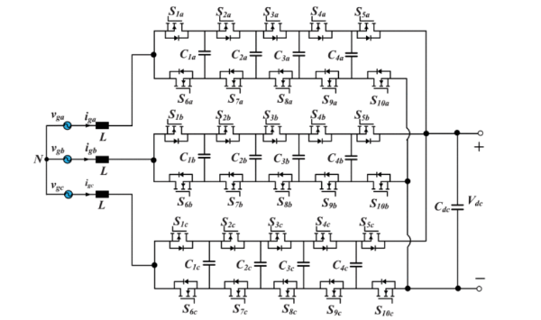
Fig. 2: Three-phase 6-level flying capacitor multilevel ac-dc converter. Source: IEEE Access
Another benefit of FCMLC is that it only needs a modest amount of PWM modulator because it has a high switching node frequency and doesn't use PWM frequency, which leads to higher PWM resolution
Neutral Point Clamped Multilevel AC-DC Converter
Neutral point clamped (NPC) AC-DC converters are another type of MLC that have
- Low total harmonic distortion
- Medium-voltage operation
- Less dv/dt stress across the switch
- Low output voltage waveform distortion.
Fig. 3 depicts a three-phase, three-level NPC ac-dc converter.
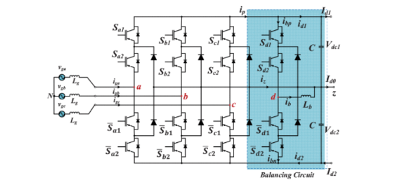
Fig. 3: Three-phase neutral point clamped rectifier. Source: IEEE Access
NPC Topology with Bipolar DC Bus
Researchers have presented a novel EV charging station design. This design integrates a central AC-DC converter with NPC topology, connecting it to the medium voltage grid on one side and the bipolar DC bus on the other side.
Advantages
Using NPC in conjunction with a bipolar DC bus has various advantages.
- Less step-down effort is required by the DC-DC fast chargers
- Increased reliability
- Increased charging station power capacity
Disadvantages
Unlike unipolar bus architectures, bipolar DC bus structures have worse unbalancing issues. Unpredicted car arrivals and battery technology worsen the unbalancing situation. Adding a voltage-balancing circuit to the three NPC topology legs solves this problem.
Three-Level Stacked NPC
A three-level stacked NPC is highlighted as an AC-DC power stage that performs better than a three-level NPC.
Advantages
- Higher switching frequency
- Better overall loss balancing
Disadvantages
- Asymmetric power loss distribution
- Issues with the thermal control system.
Active NPC Topology
Because of the issue mentioned above, active NPC (ANPC) topology—a variation of NPC topology—is created, which employs extra active switches in antiparallel to NPC diodes.
Advantage
ANPC reduces the unequal distribution of conduction and switching losses among the switches.
Disadvantage
However, because there are so many switches, implementing control is difficult due to the requirement for a linked gate drive circuit for each switch.
Summarizing the Key Points
- Multilevel converters offer enhanced power efficiency in electric vehicle charging stations, achieving high-power demands with improved reliability.
- Utilizing advanced topologies like cascaded H-bridge, flying capacitor and neutral point clamped topologies optimizes power delivery.
- It explores modulation techniques like sinusoidal pulse width modulation and space vector pulse width modulation for efficient power delivery.
- By addressing challenges like voltage balancing and component reliability, multilevel converters pave the way for efficient and reliable fast charging solutions in the electric vehicle industry.
Reference
Safayatullah, M., Elrais, M. T., Ghosh, S., Rezaii, R., & Batarseh, I. (2022). A Comprehensive Review of Power Converter Topologies and Control Methods for Electric Vehicle Fast Charging Applications. IEEE Access, 10, 40753–40793. https://doi.org/10.1109/access.2022.3166935