LEDs only rely upon accurately regulated current, through the semiconductor junction, to produce light, where the relative voltages at the terminals to the system ground (or chassis in an automotive system) are unrelated. As a result, LED systems can take advantage of the different topologies offered by switching technologies.
In many systems, including the myriad of regulators deployed in automotive power delivery systems, the design of power conversion regulators is often a difficult and complex task. This article aims to simplify the selection process by explaining the benefits, tradeoffs, and applications for different switching topologies used for LED drivers.
LEDs are unlike traditional electrical light-producing filament or gas components. Utilizing specific semiconductor junctions, LED manufacturers can produce specific colors of light spanning the entire visible range, as well as IR and UV. In automotive applications, LEDs can increase the safety in both daylight and nighttime driving scenarios. Increased efficiency can extend battery life in electric vehicles, and multiple LEDs in a single system can eliminate single-component failures.
Due to their versatility, LEDs offer the capability of being driven in many different ways. Because the output from LEDs is well-controlled light, LED loads are unlike traditional loads to a power system. LEDs only rely upon accurately regulated current, through the semiconductor junction, to produce light, where the relative voltages at the terminals to the system ground (or chassis in an automotive system) are unrelated. As a result, LED systems can take advantage of the different topologies offered by switching technologies.
How to select the correct switching topology for automotive LED systems
The choice of a particular switching topology in an automotive system is related to the complete system design. Considerations should be taken into account for minimum input voltage, maximum string voltage, chassis return capability, shorted output capability, maximum input current, output/LED current, and PWM dimming.
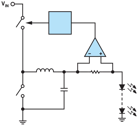
Step-down (buck) converters
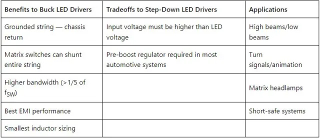
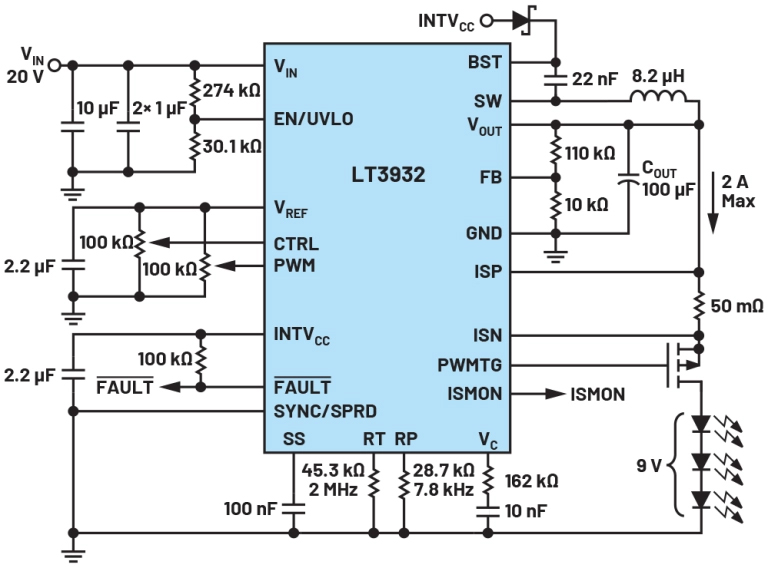
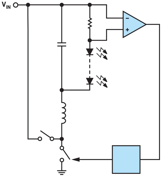
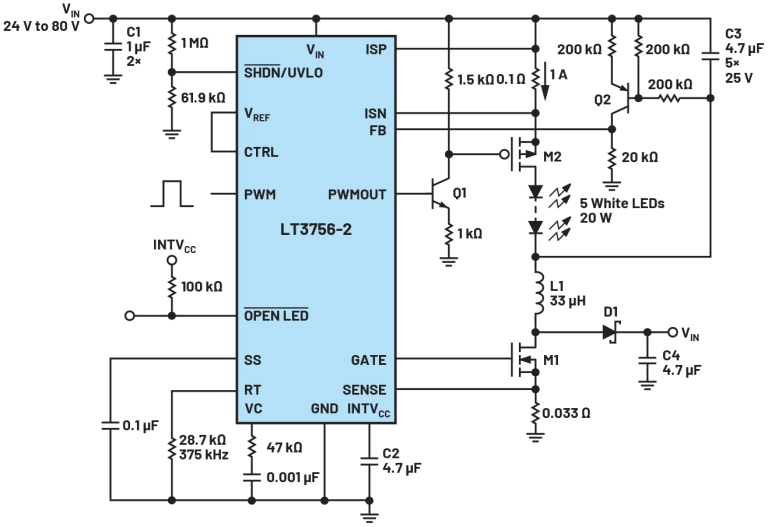
Step-down (or buck) LED drivers regulate the current in an LED string from a voltage that is higher than the total LED string voltage. Buck LED drivers can be safely shorted to the system ground, making them both intrinsically safe. They can have the capability of chassis return (one wire for power), and they can easily be adapted to matrix or animation applications. Figure 1 and an example schematic in Figure 2 show basic system diagrams with the controller modulating the high-side switch for current control.
Several critical features to look for in step-down LED drivers are fixed-frequency operation, high efficiency through excellent switching control and low resistance switches, high accuracy throughout the analog dimming range, and, for excellent EMI, a properly designed spread-spectrum frequency modulation.
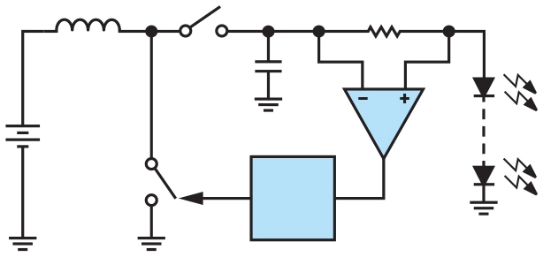
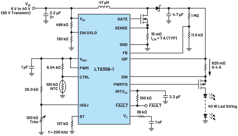
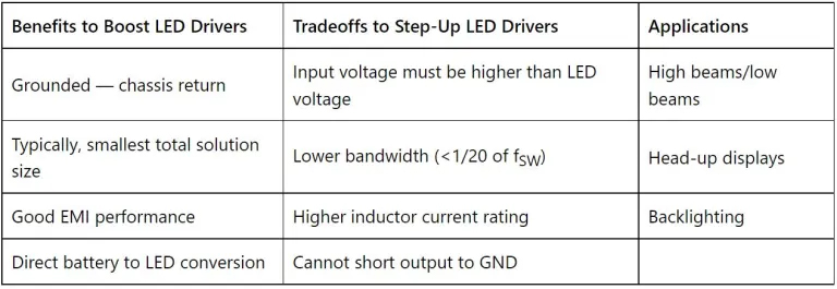
Step-up (boost) converters
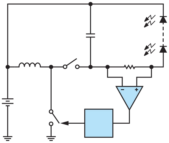
Step-up (or boost) LED drivers regulate the current in an LED string from a voltage that is lower than the total LED string voltage. This is useful in many automotive systems, where many LEDs need to conduct in a single string. Typical 12-V automotive systems have operational ranges from 6 V to 18 V, requiring that the LED driver runs down to 6 V, providing large step-up ratios for the LEDs to remain illuminated. Figure 3 and an example schematic in Figure 4 show basic system diagrams with the controller modulating the low-side switch for current control.
Boost-buck using a boost converter
Some step-up (or boost) LED drivers may be configured to return the LED cathode to the supply. This configuration is referred to as buck-boost. The total output voltage is VIN (VBATTERY), which is added to the total LED string voltage. The benefit of this topology is being able to drive an LED string that is higher, lower, or equal to the supply voltage. The limitations of this topology are only bounded by the converter — on the low end by the minimum supply voltage of the controller IC and on the high end by the controller IC’s maximum output voltage.
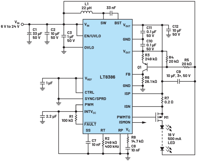
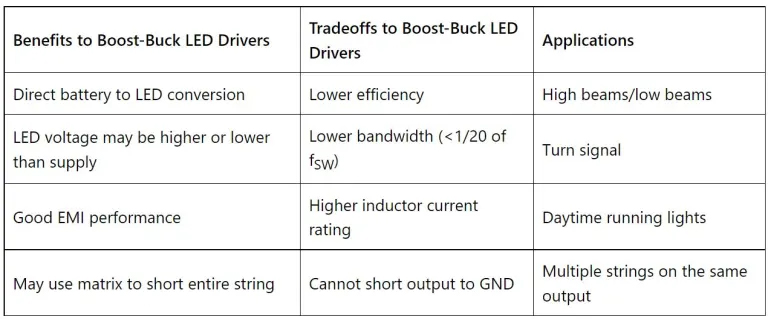
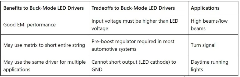
Buck mode using a boost converter
Some step-up (or boost) LED drivers may be configured to step-down from the supply (rather than ground referenced, as in a standard buck), creating a buck-mode configuration. This configuration has the same limitations as a buck, where the total LED string voltage must be less than the input supply.
Buck-boost converter
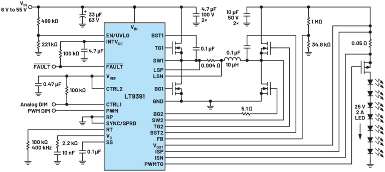
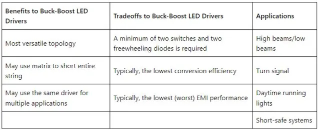
Buck-boost LED drivers regulate LED current from a supply that is higher or lower than the total LED string voltage. The converter modulates the high-side switch connected to the input voltage in the step-down mode and the low-side on the output side in step-up mode. This topology is the most complex but also the most flexible. VIN and VOUT ranges are limited only by the controller IC. This is a good choice for matrix applications.
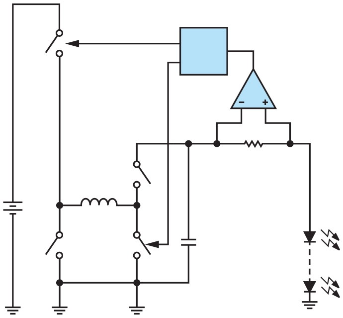
Conclusion
Automotive LED lighting systems can be driven with switching regulators in many different ways. Depending on the application, the selection of switching topology and configuration allows the lighting designer to create complete subsystems for the different lighting requirements throughout an automobile. Selecting the correct power conversion switching topology and configuration for the system optimizes requirements such as complexity, efficiency, EMI, and safety.