Power Electronics News explores the importance of wireless power transfer (WPT) systems coil configurations such as the IH-WPT configuration.
Wireless power transfer (WPT) systems are becoming more and more popular, with significant applications in the consumer electronics, medical device, and electric-vehicle charging sectors. Among the different aspects involved in the design of WPT systems, one of the most relevant regards the coil-coupling configuration, or architecture. For high-frequency resonant WPT systems, the two-coil and four-coil configurations (without ferrites) are commonly used. However, in the case of medium-frequency WPT systems, ferrites are used to improve the wireless-power–transmission efficiency in near-field wireless charging applications, with a consequent increase in the weight and cost of the solution. Finally, short-range closely coupled WPT systems are normally free of ferrites, thus achieving a reduced cost and weight at the expense of a reasonably lower efficiency. Coil design plays a fundamental role in WPT systems, as it affects several aspects, including system behavior, efficiency, misalignment tolerance, and bandwidth of operation frequencies.
Coil configurations
A 3D view of two different two-coil configurations is shown in Figure 1. The conventional WPT coil configuration, consisting of two identical flat-spiral coils well aligned and separated by approximately zero distance, is shown in Figure 1a. The presented interleaved helical WPT (IH-WPT) configuration, shown in Figure 1b, consists of a coil pair with coaxial helical coils, with one coil inserted inside the other, which has a slightly larger diameter. The two coils can be aligned easily and maintain alignment even under vibration and shock, due to the small air gap between them. Finally, the configuration obtained inserting a flat-spiral coil inside another helical coil is shown in Figure 1c.

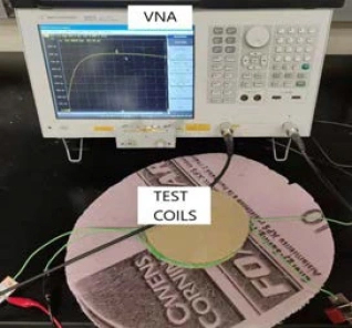
To provide a better comparison and evaluation, all of these configurations have been evaluated with frequency below 1 MHz (30 kHz to 1 MHz) and for short-distance values, using coils made with almost equal self-inductance and diameter values. To obtain the S-parameters, an experimental setup based on a vector network analyzer (VNA) was used (Figure 2).
Modeling of the two-coil WPS system
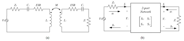
Because the two-coil WPT configurations are normally designed and analyzed as a single-input single-output system, their model can be reduced to a two-port network model. The lumped circuit model is shown in Figure 3a, where VS and ZS are the voltage source and impedance, respectively, whereas C1 and C2 are optional tuning capacitors placed in series with wireless coils, L1 and L2 are the self-inductances of the two coils, and M is the mutual inductance between the two coils. ESR is the equivalent series resistance, given by the sum of the coil ESR and the resistance of the tuning capacitor. The two-port network model is shown in Figure 3b, where the WPT system is represented by the S-parameter matrix.
Through proper calibration and system settings, the relationship between source impedance, load impedance, and nominal characteristic impedance, respectively, is as follows:
Zs = Zl = Z0 = 50 Ω
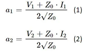
The incident waves of Ports 1 and 2 are given by:
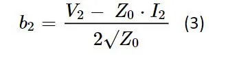
Likewise, the reflection wave of Port 2 is given by:
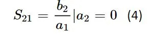
While the parameter S21 is expressed by:
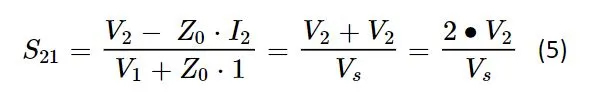
Now, by substituting Equations 1 and 3 into Equation 4, the S21 parameter can be obtained as given by:
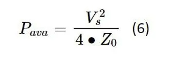
Because the source impedance (Zs) and the nominal characteristic impedance (Z0) are the same, the maximum available power from the source (Pava) can be obtained using the maximum power transfer concept given by the following equation:
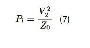
While the load power is given by:
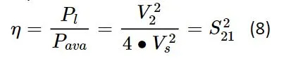
Finally, the efficiency of the WPT system can be obtained as follows:
Experimental results and comparison
To assess the efficiency of the WPT system, the scattering parameter S21 can be used and measured through the VNA. Its value can be measured with the network analyzer equipment in all of the three relevant WPT coil configurations shown in Figure 1. The plot of the power transmission efficiency as a function of frequency, for different coil configurations, is shown in Figure 4. The best results are obtained with the IH-WPT configuration, which achieves a peak efficiency value above 70%, followed by the flat to flat and by the flat in helical configurations.
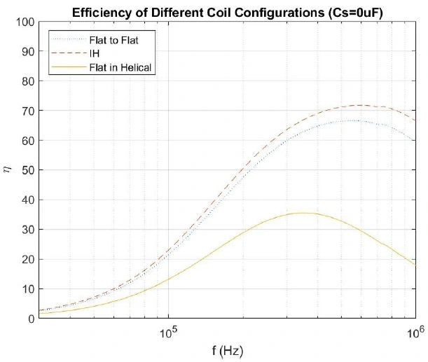
Figure 5 shows how the power-transfer efficiency of the conventional flat-pair configuration is affected by the misalignment conditions, limited to a range between 0 and 3 cm. As expected, the peak efficiency value is obtained when the misalignment is null, while efficiency decreases as the amount of misalignment increases. The highest efficiency values for these three configurations are measured within the frequency range from 300 kHz to 600 kHz.
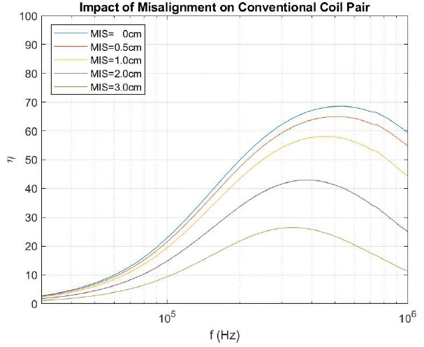
As shown in Figures 4 and 5, the conventional flat-spiral-coil–pair configuration achieves a peak efficiency value of about 68% (without ferrite and when the coil pairs are well-aligned) at a frequency of 490 kHz. Nevertheless, the efficiency value decreases rapidly as the misalignment between the transmitter coil and the receiver coil increases. The IH-WPT configuration archives a peak efficiency value of about 72% at the frequency of 530 kHz.
Conventional silicon-based switching power devices (such as power MOSFETs, IGBTs, and power diodes), as well as common inverter and rectifier circuit configurations (such as half-bridge and H-bridge inverters and rectifiers) can operate effectively inside this frequency range, providing high power-transfer–efficiency values.
Due to its particular and unique geometry, the IH-WPT configuration offers the benefit of easily achieving and maintaining the alignment between the transistor coil and the receiver coil. The configuration shown in Figure 1c, the flat spiral coil placed inside a helical coil, offers a much lower efficiency compared with the other two configurations.
In conclusion, we can say that the proposed IH-WPT configuration consisting of one helical coil inside another larger helical coil offers two main advantages over the conventional flat-spiral-coil–pair configuration. The first advantage is that it provides higher wireless-power-transmission–efficiency values, while the second advantage is that it can easily achieve and maintain alignment between the transistor coil and the receiver coil.


