Households and workplaces have become some of the most common places to spend most of our day. Regardless of the size or space available, it is imperative that these spaces be made as comfortable as possible to have a suitable environment. The key to indoor comfort is to keep the space at a constant temperature. Temperature changes can cause pain, decreased productivity, and even health problems, whether at home or at work. Fortunately, you can build a straightforward room temperature controller that will maintain a suitable temperature in your home all year long with the aid of an Arduino microcontroller and a few components.
The Arduino microcontroller is one of the most commonly used microcontrollers by both engineers and hobbyists due to its cheap value, effectiveness and open community that can help with troubleshooting. The user base for Arduino has continually grown and its application also become almost limitless. Based on the fact that Arduino is open source more hardware and devices are developed by independent developers for specialized functions.
For most people in areas where the weather is unpredictable, this project is important as it achieves the same goal as an expensive HVAC system. At the heart of this system is the Arduino Uno, a small computer that can be programmed to perform a wide range of tasks. To read the temperature, we'll be using a DHT11 temperature and humidity sensor. This component is designed to detect changes in temperature and humidity and send that data to the Arduino for processing.
Why Use an Arduino Controller for the Temperature Controller?
For this project, we will need a heater and fan to regulate the temperature, and a relay module will do this. Relays are simply low-voltage electronic switches that may be activated by a signal. The Arduino will trigger the relay to switch on the heater when it determines that the temperature is too low. In contrast, the Arduino will instruct the relay to activate the fan if the temperature rises too much.
This project's simplicity is what makes it interesting and practical. It is also important to note the inexpensiveness of both the Arduino and the components used. The project is great for beginners because the Arduino code needed to manage the device is rather simple. The system will start sensing the temperature and regulating the fan and heater as soon as you have hooked everything up and uploaded the code to the Arduino. Additionally, you can quickly change the code to meet your unique requirements thanks to Arduino's great degree of customization.
What you will need
As previously said, this project will involve the software, code, and hardware components. One must comprehend the fundamentals of electronics and basic circuits in order to use Arduino and other electrical components. For further information on this, see our articles on Arduino, microcontrollers, and the fundamentals of electronics.
Here are some of the requirements:
Requirements
- Arduino Uno
- 2- relay modules
- 1- 240v AC Fan
- 2000W 240V Heater
- Temperature sensor
- Jumper Wires
- Breadboard
- Power supply (9v,12v and 240v)
- USB cable for Arduino Uno (to connect it to your computer for programming)
- Computer with Arduino IDE software installed
Having these components and tools ready will allow you to begin the wiring, programming, and testing process for the room temperature controller project.
- Arduino Uno: This is the microcontroller board that will be the brain of the system. The Arduino Uno is widely available and relatively inexpensive. It has several input/output pins that can be used to control various components.
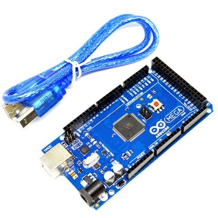
Figure 1: Arduino Mega, an alternative to Uno
- DHT11 temperature and humidity sensor: This is a basic sensor that can measure temperature and humidity levels in the room. It is a digital sensor, meaning that it communicates with the Arduino using digital signals. The sensor has four pins, including VCC, GND, Data, and NC (not connected). It can measure temperatures from 0-50°C with an accuracy of ±2°C.

Figure 2: DTH11 Temperature and Humidity Sensor
- Relay module: This component is used to control the fan and heater based on the temperature readings from the sensor. The relay module is essentially an electronic switch that can be controlled by a low-voltage signal. It has several input pins, including VCC, GND, and Signal, and several output pins for connecting the fan and heater.

Figure 3: Relay
- Fan: When using a relay to control the fan, there are a variety of fans that can be used, both DC and AC fans. A small DC fan is used to cool down the room when the temperature is too high. The fan should be rated at 12V and draw no more than 200mA. Alternatively, one could use a normal AC house fan which is cheaper and easily accessible. These normally operate at 110/240V.
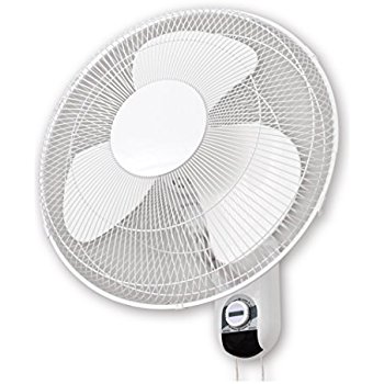
Figure 4: Common Household Fan
- Heater: Similarly, heaters can be found in a variety, ranging from DC heaters to AC heaters with different power ratings. A small ceramic heater can be used to warm up the room when the temperature is too low. The heater should be rated at 12V and draw no more than 500mA. Alternatively, a more easily accessible house AC heater can be used.
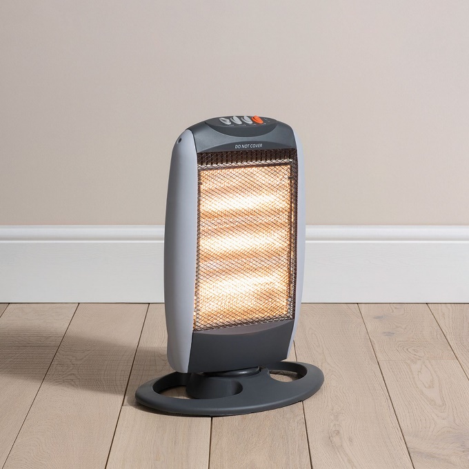
Figure 5: Common Room Heater
- Jumper wires: These are used to connect the various components. You will need several male-to-male, male-to-female, and female-to-female jumper wires.
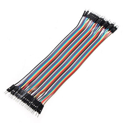
Figure 6: Jumper Cables
- Breadboard: This is a prototyping board that allows you to easily connect and test electronic components. It has several rows of interconnected pins that allow you to create a circuit without soldering.
Getting Started
Wiring
Here is a thorough explanation of the wiring for the Arduino-powered electronics.com/productdetail/sgmicro-sgm809xxn3tr-20982402">www.jakelectronics.com/solution/simple-room-temperature-controller-with-arduino">room temperature controller project:
- Gather the following parts first: an Arduino Uno, a DHT11 sensor, a relay module, a fan, a heater, jumper wires, and a breadboard.
Assemble the Arduino board and the DHT11 sensor:
- Connect the Arduino's 5V pin to the DHT11 sensor's VCC pin.
- Connect the Arduino's GND pin to the DHT11 sensor's GND (ground) pin.
- Connect any Arduino digital pin to the Data pin of the DHT11 sensor.
Relay module to Arduino board connection:
- Connect the Arduino's 5V pin to the VCC pin of the relay module.
- Connect the Arduino's GND pin to the GND pin on the relay module's GND (ground) pin.
- Connect any digital Arduino pin (for example, pin 3 for the fan relay and pin 4 for the heating relay) to the Signal pin of the relay module.
Relay module and heater connected:
- One heater wire should be attached to the relay's normally open (NO) terminal, which is located on the heater pin of the relay module.
- The other heater wire should be connected to the common (COM) relay terminal, which is located next to the heater pin on the relay module.
How to power an Arduino board:
- Connect the Arduino board to the USB cable's other end.
- The other end of the USB wire should be connected to your computer or an appropriate Arduino power supply.
Alternatively, for a neater setup, if using a breadboard, you may connect the components using jumper wires on the breadboard.
Code
The code for the room temperature controller with Arduino is responsible for reading temperature data from the DHT11 sensor and controlling the fan and heater based on the temperature readings. Here is a brief overview of the code:
- Included in libraries:
The needed libraries are first included in the code. To operate with the DHT11 sensor in this instance, the DHT library is provided.
- Definitions for variables and pins:
The DHT sensor type, fan and heater relay pins, and DHT sensor pin constants are all defined in the code.
- Goal and Setup:
A DHT class instance is generated with the proper pin and sensor type.
The relay pins are configured as output pins and the serial communication is initiated in the setup procedure.
- Loop:
Using the readTemperature () function, the main loop function begins by reading the temperature from the DHT sensor and saving it in a variable.
- Logic for Temperature Control:
Based on the temperature reading, the appropriate action is chosen using a sequence of if-else expressions.
Setting the fan relay pin to HIGH and the heater relay pin to LOW activates the fan if the temperature falls below a certain threshold.
Setting the fan relay pin to LOW and the heater relay pin to HIGH disables the fan if the temperature rises over a different threshold.
By setting both relay pins to LOW, the fan and heater are both switched off if the temperature is within the required range.
- Delay:
A one-second delay is built into the code before the next temperature reading is taken. As a result, there are no sudden changes and measurements are spaced reasonably.
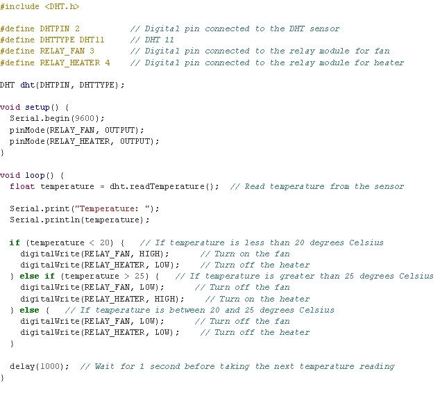
Figure 7: Simple Room Temperature Controller Code
Testing and Troubleshooting
- Upload the code to the Arduino Board
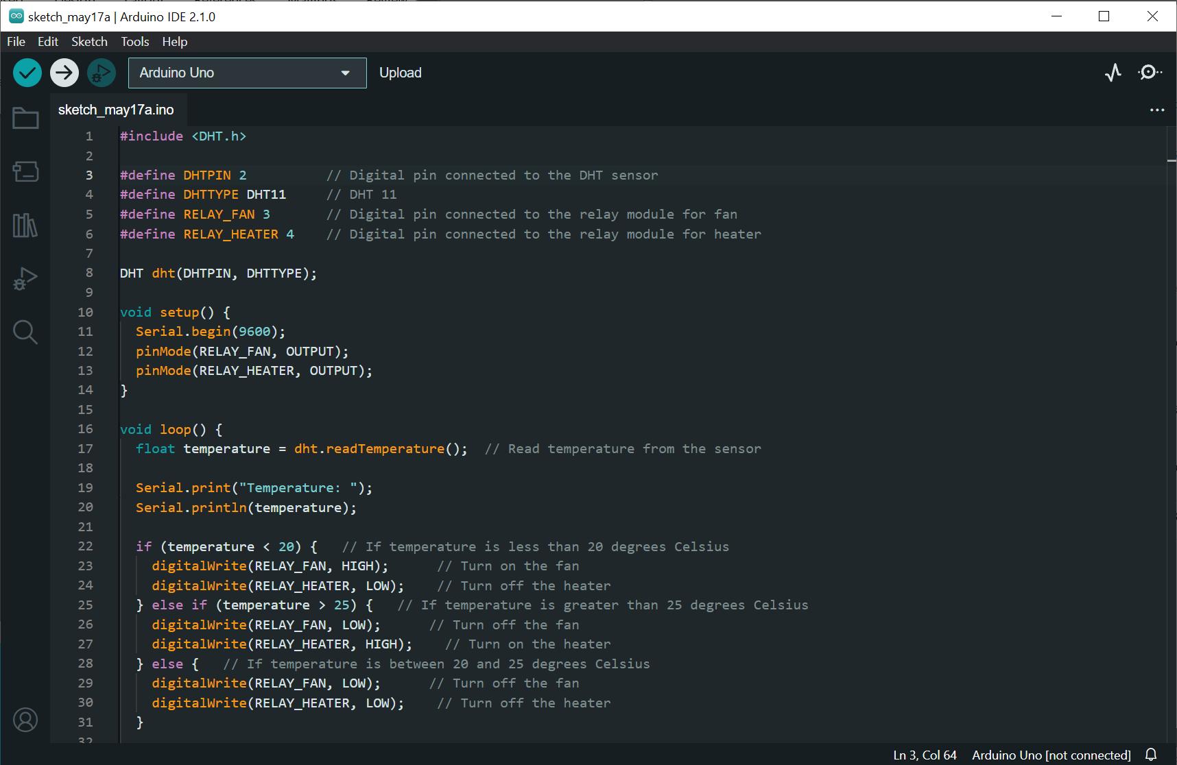
Figure 8: Upload the code to the Appropriate device
- Monitor the serial output on the serial monitor on the Arduino IDE, and observe the behaviour of the fan and heater depending on the temperature fluctuations.
- Adjust the code or the circuit if necessary to achieve the desired functionality.
- Troubleshoot any issues such as incorrect wiring, component failures, or incorrect code logic.
Once the code is configured and working, one can modify it to better fit their needs and provide additional customization. It is crucial to building an enclosure and a location to attach the setup if this project is to serve as a long-term fix for an existing issue. This increases the system's dependability while also ensuring safety.
Final Thoughts
In conclusion, creating a straightforward Arduino room temperature controller is a doable and worthwhile project for novices. Using parts like the DHT11 sensor, relay module, fan, and heater, you may build a system that regulates a room's temperature automatically.
As a starting point, the given code enables the Arduino to read temperature information from the sensor and regulate the fan and heater accordingly. To ensure optimal operation and fit your unique requirements, it's crucial to alter the code and wiring.
Always verify your connections before turning on the system and be careful when working with electrical components. To attain the best level of comfort in your home, enjoy the process of learning, trying, and refining your room-temperature controller.