TWT (Travelling Wave Tube) comes from the close interaction between an electron wave and the RF signal to be amplified
Earlier this year, the James-Webb Space Telescope sent back to Earth some of the most detailed images of other galaxies. This was partly due to a Vacuum Electronics Device (VED) called the Travelling Wave Tube Amplifier (TWTA), which was part of the microwave amplification system used on the telescope and the ground station. TWTs have a history going back over 80 years, before WWII. Some brilliant RF engineering pioneers such as Haeff, Lindenblad, Kompfner and others are credited with the invention and improvement of this device back in the 1930s and 1940s. However, it was during peace times, post WWII that the usage of TWTs increased dramatically. They were used for creating microwave ground relay stations and on communication satellites such as Telstar, Intelsat, Inmarsat etc., and helped create the global communication networks we are used to today.
TWT is also used on all deep space probe missions such as Voyager and Cassini. Today there are thousands of TWTs in orbit, as well as in satellite ground stations. TWTs are also widely used in electronic warfare, such as guidance systems as well as radar systems. Thales, Stellent, NEC, Teledyne e2V and others are the dominant providers. Current estimates put the market value for TWTA’s at around $1B, with a low single-digit annualized growth rate.
Operation Principle of TWT
The beauty of the TWT comes from the close interaction between an electron wave and the RF signal to be amplified. A simplified view of one of the common versions of this device called the Helix TWT is shown in Figure 1.

The electron wave is generated in an electron source consisting of a heated cathode, with temperatures reaching around 1000oC. An Ultra High Vacuum (<10-8 Torr) is present in the tube. An HV, typically 4-120 kV applied between the anode and cathode, creates the beam, while a focus or control grid helps guide the beam into the next part of the device. An Electronic Power Conditioner (EPC) converts the satellite bus voltage to provide the regulated HV needed for the electron source. The Slow Wave Structure (SWS) is where the RF input wave is slowed down using the Helix as a delay line, with the goal being to match the wave velocities of the electron beam and the RF wave. A periodic permanent magnet in the SWS focuses the electron beam toward the device axis.
Velocity modulation of the electron beam, as it interacts with the helix, creates electron bunching and a positive feedback mechanism with amplification of the RF wave as momentum lost from the electron beam is transferred to the RF wave through the principle of momentum conservation. The helix provides a low impedance path for the RF wave and may be composed of low O2 Cu, for example. Attenuators that prevent oscillations and reflections can separate various helix sections and maintain wave stability.
3D Electromagnetic simulations can be used to optimize the cavity and helix; for example, the pitch of the helix can vary along the tube length to match the electron wave velocity change. Ceramic rods, for example, made of BeO can support the helix and provide heat transfer. The last stage is the collector, which absorbs the remaining electron energy and converts it to heat. Creating a multi-stage depressed collector makes it possible to recover a lot of the electron energy and improve overall efficiency. An Example RF output vs. input curves is shown in Figure 2a.
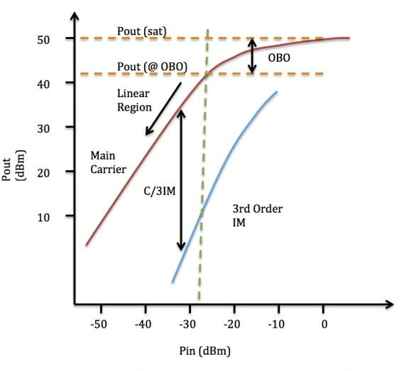

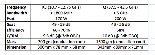
The device has a linear range where most small signal amplification could be done with low distortion. An Output Back Off (OBO) is used to operate the device below its saturated power level, and C/3IM shows the S/N to the 3rd harmonic wave. Figure 2b shows an example plot of efficiency and power vs frequency for a Ku-band TWTA. Linearizers can be used with the TWT, as shown in Figure1, which shows a Linearizer Channel Amplifier (LCAMP). LCAMPs include a digital or hardware pre-distorter that can adjust the RF input, compensating for the tube’s non-linearity, to provide either a constant gain or output level. Table 1 shows some of the basic specifications from TWTA’s provided by one of the manufacturers at the Ku and Q frequency bands.
The manufacture of space TWTA’s is a precision handcraft process that can take several months and requires tuning cycles at room temperature and hot and cold temperatures. Costs can range from several thousand to hundreds of thousands of dollars per TWTA.
Advantages of TWTA and comparisons to Solid State Power Amplifiers (SSPA)
One of the most useful features of TWTA’s that led to its widespread use early on is its high bandwidth (BW) and low noise figure. As opposed to resonant VEDs such as Klystrons, which have limited BW and are sensitive to structural spacing, the TWTA’s provide higher BW (typically exceeding 2 octaves) at frequencies ranging from 300MHz to several 100 GHz, high gains (up to 70db) and peak powers that can range from 10’s of W to several 1000’s of kWs. Compared to Helix TWTA’s, Coupled cavity TWTA’s are a version that can provide higher power with lower BW. In recent years, SSPA, particularly GaN-based ones, have replaced TWTA’s in some of the traditional TWTA application space. Microwave relay stations, Low Earth Orbit satellites, such as OneWebTM, now rely mostly on SSPA. Table 2 provides a comparison between the TWTA and SSPA.
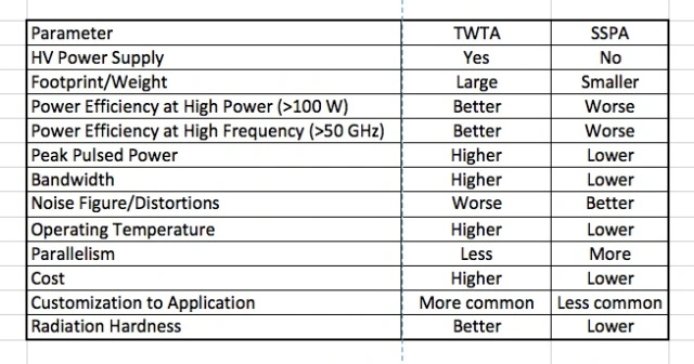
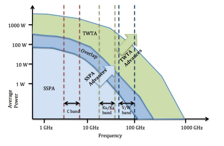
SSPA’s can provide a lower size, weight and cost advantage and dominates usage in the C-band Band [1], with accelerated usage at higher bands like Ku/Ka, but with TWTA’s still dominating this higher frequency space. SSPA’s can provide better linearity than TWTA’s [2]. Disadvantages of SSPA, however, include large heat generation and the complexity involved in paralleling multiple devices, especially at the higher power/frequency space, along with decreasing efficiencies in this space. TWTAs can have conduction or radiation cooling and are much more stable at high temperatures. A study in 2007 [3] estimated that 69% of all Geo-Stationary Satellites exclusively used TWTA’s, with 24% using a hybrid TWTA/SSPA combination. Figure 3 shows a Power/Frequency usage space for the SSPA and TWTA. Both devices are extending their usage envelope.
The future
There are several innovations that will ensure TWTA usage far into the future, some of which are listed below:
- Extension to Q/V and W bands: Satellite communication networks aim to provide “Terabit Connectivity” with High Throughput Satellites (HTS). To facilitate this, the frequency will be increased from the current Ku/Ka bands (20/30 GHz) to the Q/V bands (50GHz for uplink and 40 GHz for downlink) [4]. Several manufacturers, such as NEC [5] have demonstrated TWTs in this frequency space. Further out in frequency, the European Commission H2020 TWEETHER project plans to use the W band (92-95 GHz) for point-to-multipoint transmission hubs and TWTs are planned for this [6].
- Mini-TWTs: These are smaller versions, with lengths as small as 7 inches and are typically integrated with SSPA amplifiers to work as the final gain stage in a Microwave Power Module (MPM). These much lighter mini-TWTs typically work at lower cathode voltages (< 8kV) and current densities (<3A/cm2) to provide better lifetimes. The SSPA preamplifier compensates for lower gains from the TWT. Such MPMs have been used, for example in pulsed phased array radar systems [7]
- Flex-TWTs: The goal here is to make the TWTs remote-controlled from ground stations to vary frequency and power levels. Power level control through anode voltage changes and frequency modulation through the helix and collector voltage change has been demonstrated [8].
References
[1] W. Lohmeyer, et al., “Communication satellite power amplifiers: current and future SSPA and TWTA technologies”, International Journal of Satellite Communications and Networking, 2015
[2] X. Jing, et.al, “A Comparison of SSPA and TWTA for Beidou Navigation Satellite Systems”, 2021 Int. Conf. Microwave and Millimeter Wave Technologies
[3] K. P. Mallon, “TWTAs for satellite communications: past, present, and future”, IEEE Int. Vacuum Electronics Conf., 2008
[4] G. Codispoti, et. al., “Validation of ground technologies for future Q/V band satellite systems: the QV-LIFT project,” IEEE Aerospace Conf., 2018
[5] N. Kosugi, et. al., “NEC Network and Sensor Systems Ltd Q/V Band Helix TWT for Future High Throughput Satellite Uplink Applications,” 2020 IEEE 21st Int. Conf. Vacuum Electronics
[6] F. Andre, et. al., “W-band TWT for High Capacity Transmission Hub for Small Cells Backhaul,” 2018 IEEE Int. Vacuum Electronics Conference
[7] T. Muhehiro, et. al., “Development of an X-band 800W Pulsed Mini-TWT for Active Phased Array Radar Modules,” 2014 IEEE Int. Vacuum Electrons Conference
[8] E. Cuignet, et. al., “Very High efficiency Dual Flexible TWTA, a flexible concept allowing to deal with performances and schedule constraints of telecommunications Payloads,” 2013 IEEE Int. Vacuum Electrons Conference