Thermal paste, also known as thermo-conductive paste, is essential to improve heat exchange between electronic components and heatsinks
Thermal paste is indispensable in an electronics workshop. Thermal paste is a dense compound used to improve heat exchange between electronic components and heat sinks. In an electronic system, in fact, not all energy is used in a process and a more or less important part is lost in heat. In this article we discover some of the secrets of using thermal paste, otherwise known as thermo-conductive paste.
Thermal Paste
Today, heat exchange between electronic components and heat sinks is of paramount importance. The devices must be operated at a temperature as far away as possible from the fateful Tj(max). The relevant datasheets, in fact, state that operation at high temperatures could degrade the quality of the work performed, with a huge amount of power lost in heat and a drastic lowering of the overall system efficiency. In one of the previous articles, we looked at the general uses of the main thermal paste, along with some cheap substitutes. Even if the heatsink is perfectly adhered to the CPU, tiny roughness and imperfections always remain, decreasing the useful dissipation surface. Thermal pastes help and facilitate heat dissipation between these two parts by actually increasing the useful dissipation surface. Of course, it is always advisable to prefer first-rate compounds, certified by the companies for optimal operation and efficient heat exchange. Usually, thermal paste is composed of zinc oxide and silicone and facilitates the interconnection between the chip and its cooling system. Its function is therefore vital, although many people underestimate its usefulness. Without it, air bubbles would form, limiting heat exchange. Thermal paste, on the other hand, fills in microscopic surface imperfections, facilitating cooling of the device. Figure 1 shows the different types of adhesion between the two contact surfaces (the CPU and the heatsink). In particular:
- the first figure shows an ideal adhesion, which is impossible to achieve in reality
- the second figure shows a real adhesion without the use of thermal paste, in which the two surfaces are not perfectly smooth and the microscopic imperfections contain air, which prevents the passage of heat
- the third figure shows a real and improved adhesion with the use of thermal paste.
Note the different thermal conductivity coefficients, depending on the type of material treated and used.

Thermal conductivity
Thermal conductivity is a physical quantity that measures the ability of a substance to transmit heat through thermal conduction, a phenomenon that manages the transport of heat. It depends on the nature of the material, but not on its shape. Thermal conductivity is denoted by the letter ‘k’ and its unit of measurement is watts per meter per kelvin:
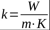
Each material therefore has its own thermal conductivity value. The higher the coefficient, the more heat is dissipated. Metals, which are excellent thermal conductors, conduct heat very well and have high thermal conductivity values. In contrast, other materials such as wood, ceramics, plastics and glass are examples of thermally insulating materials and poor heat conductors. The following table shows the thermal conductivity values of some materials.
| Material | Thermal conductivity at 20° C (W/mK) |
| Steel with 5% Ni | 29 |
| Steel with 30% Ni | 105 |
| Water | 0.63 |
| Alcool | 0.21 |
| Aluminum | 210 |
| Air | 0.026 |
| Coal | 0.15 |
| Marble | 2.8 |
| Gold | 300 |
| Porcelain | 0.9 |
| Copper | 302 |
| Cork | 0.051 |
| Glass | 0.7 |
| Thermal paste | 7.5 |
As can be seen in the table above, aluminium, air, copper and a generic thermal paste are highlighted. The respective thermal conductivity coefficients are as follows:
- Aluminium: 210 W/mK
- Copper: 302 W/mK
- Air: 0.026 W/mK
- Thermal paste: 7.5 W/mK.
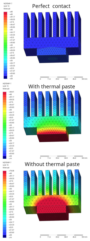
Aluminium and copper, being metals, are excellent thermal and electrical conductors. Air is a very poor thermal conductor and is what hinders heat dissipation when it accumulates between an electronic component and its heat sink. In practice, it is almost an insulator and hinders heat exchange to the maximum. Thermal paste does not have the same values and performance as aluminium and copper, but nevertheless makes an excellent contribution to heat transfer. Depending on the quality and material used in the thermal paste (zinc or silver), it can have a conductivity coefficient of between 2 W/mK and 8 W/mK. Figure 2 shows a generic simulation with three different operating configurations. Supplying a power of 48 W on the lower side of the system causes the CPU and heatsink to heat up at an ambient temperature of 20° C. The first illustration refers to an ideal configuration, in which the contact between the CPU and heatsink is perfect, even at the molecular level. In this case, the maximum temperature reached by the system (precisely on the CPU) is 40° C. The second illustration refers to a configuration using thermal paste. In this case, the maximum temperature reached by the system, on the CPU, is 44° C, slightly higher than the previous one, but still very acceptable. The third illustration refers to a critical configuration, in which the contact between the CPU and the heatsink is precarious, without the use of thermal paste and with the presence of many air bubbles between the two parts. In this case, the maximum temperature reached by the system, on the CPU, is 78° C. In this case, operation of the CPU takes place at a high temperature, for which the designer must be very careful.
The dissipation space is very important
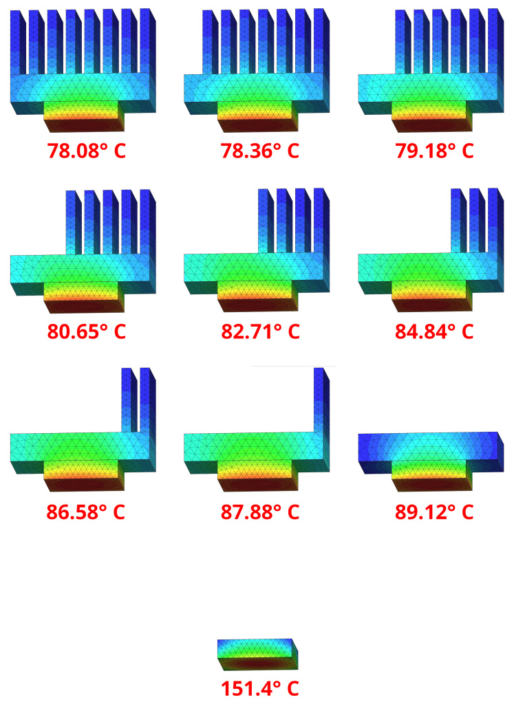
One of the most important aspects not to be forgotten is the heatsink’s dissipation space. Heat sinks are constructed in such a way as to achieve the largest surface area exposed to air. The fins and protuberances have the task of creating the largest possible exposed surface area. Figure 3 shows an example of a system, with power applied to the base always constant. In each illustration, a cooling fin and, finally, the entire heatsink were removed. As can be seen, without the heatsink elements, the temperature reached by the CPU is always higher and then reaches the extreme case where the heatsink is completely missing. The general temperatures reached by the CPU, with the same power applied to it, are as follows:
- with heatsink complete with 8 cooling fins: 78.08° C
- with heatsink fitted with 7 cooling fins: 78.36° C
- with heatsink fitted with 6 cooling fins: 79.18° C
- with heat sink provided with 5 cooling fins: 80.65° C
- with heat sink fitted with 4 cooling fins: 82.71° C
- with heat sink equipped with 3 cooling fins: 84.84° C
- with heat sink equipped with 2 cooling fins: 86.58° C
- with heatsink fitted with 1 cooling fin: 87.88° C
- with heatsink without cooling fins: 89.12° C
- without heatsink: 151.4° C.
Conclusion
Today’s electronic components are very efficient, but despite this, the temperatures reached by circuits can be significant. Computers are the least efficient machines that exist and they develop a lot of heat. To prevent unnecessary heat dissipation, the useful dissipation surface area must be increased. This can be achieved by working on the size and type of the heat sink or by using a good thermal paste.