This article describes how to design and build a low-noise, high-performance, low-cost brushed DC motor programmable speed regulator. The regulator is immune to the temperature, voltage, and motor load variation. Also, this circuit is not sensitive to the motor coil resistance, which allows using different motors in the same application without any adjustments.
The described circuit is designed specifically for devices in which a low-power brushed DC motor is used and in which the stability of the motor speed and low noise are critical. The motor speed is pre-programmed and does not require trimming after assembly, though it is possible to reprogram it to a different speed via I2C.
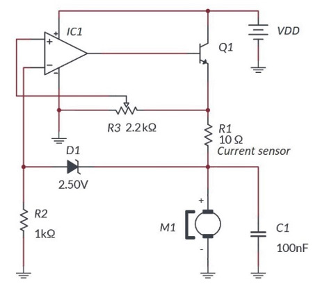
Unlike traditional circuits (see Figure 1), this design does not require any feedback sensor. In this case, the motor itself is a sensor. Other, more traditional designs (see Figure 2) are dependent on the motor coil resistance. Both require post-production trimming. Some applications (for example, audio applications) are very noise-sensitive. That makes any PWM motor controllers not suitable.

Every brushed DC motor produces interference when brushes switch from coil to coil. This is considered one of the biggest downsides of such a motor. Unfiltered, it can interrupt the normal work of the circuits powered from the same power source or simply situated close by. While it is possible to filter out to an acceptable level the interference using a capacitor connected in parallel to the motor (in some cases, ferrite coil in series), it is impossible to get rid of it completely.
In the case of the design described in this document, the small leftover interference is used to determine the motor speed. In most cases, cheap, low-voltage, low-power brushed DC motors have three moving coils. Each of them produces interference in a form of spikes; thus, the frequency of the spikes is 3× the revolutions of the rotor. So by counting the spikes, it is possible to not only determine the speed but control it by automatically adjusting to a pre-programmed value. All this and more can be achieved by using the SLG47004, a versatile programmable mixed IC with only basic external components. See the schematic diagram in Figure 3.

Design operation
Schematic design
As previously mentioned, only one chip is used in this design. The SLG47004 IC combines all necessary analog and digital macrocells in a tiny, 3 × 3-mm STQFN-24 package. See Figure 4 for a complete schematic diagram in the GreenPAK Designer project.

The complete design file can be found here. It was created in free, GUI-based GreenPAK Designer software, a part of Go Configure Software Hub.
To understand how it works, see the simplified schematic diagram in Figure 5.

The analog part is a simple voltage regulator with a power P-channel MOSFET on the output. But instead of a voltage reference, it has a digital potentiometer controlled by a digital part of the device.
The digital part consists of the ACMP, which detects the small spikes coming from motor brushes. Capacitor C2 blocks DC voltage but lets through the spikes. Amplified to a VDD level, they go to the Counter, which is set to a frequency-detection mode, where the spike frequency is compared with a reference frequency coming from the oscillator.
When the device is powered on, the resistance of the digital potentiometer is as preset, so some small voltage goes through a current amplifier (voltage regulator) built out of the op amp and P-FET and comes to the motor. It starts rotating and produces spikes. With each detected spike, the digital potentiometer resistance will increase by 1 bit, slowly increasing the motor voltage. As a result, the motor speed will rise until the spike frequency matches the reference frequency. And when it does, the counter will signal the potentiometer to decrease its resistance by 1 bit with each spike. The voltage will drop along with the motor speed. The counter will detect the frequency drop and signal the potentiometer to increase its resistance, and the cycle goes on.
In other words, the voltage on the motor rises while the spike frequency is lower than the reference frequency, and vice versa. Once the motor speed settles, the potentiometer will go up and down one step (1 LSB), keeping the speed stable within ±1 LSB. Ideally, it would take ±1 LSB to settle the motor speed, but due to the inertia, it may take up to ±50 LSB. The heavier the motor load, the more LSB it takes to settle the speed.
The frequency detector period can be calculated using the formula:

Where T is the time, RPS is the revolutions per second (RPS = RPM/60),
and n is the number of motor coils.
It should be noted that the oscillator frequency must be selected so that the counter data is close to half the counter resolution given the desired RPM (for instance, 127 for the 8-bit counter), leaving maximum headroom for regulating the motor speed.
Using a P-FET on the output of the regulator has the benefit of a very low voltage drop, allowing the VDD margin as low as 100 mV.
See Figures 6 through 9 for oscilloscope screenshots demonstrating the stability of the device at different VDD levels (yellow = test point output [PIN 12], blue = ACMP input, purple = motor DC voltage).


As an alternative design, an optical RPM feedback sensor can be used (see Figure 10). This method ensures greater motor speed accuracy and stability, as there are more pulses per revolution. The frequency detector and ACMP Vref should be adjusted accordingly. In this case, n in the formula is the number of gear tooths. The downside of this design is the cost of an extra sensor and increased power consumption.

In both designs, PIN 12 is used as a test point. Using an oscilloscope with probes connected to PIN 16 and PIN 12, it is possible to check if all input spikes are picked up by the ACMP. In some cases, the ACMP Vref should be adjusted so that every input spike is picked up and converted to a logic-level pulse.
Additional design features
The suggested design is the simplest one. Its main goal is to explain its principles.
However, the SLG47004 has plenty of unused macrocells that allow for improving performance and adding new features to the design.
For example, instead of the 8-bit counter, the 16-bit counter can be used. This will drastically improve the frequency-measuring accuracy and allow fine-tuning of the motor speed. In this case, the oscillator frequency should be increased accordingly.
Another improvement can be made by adding a feature of selecting different motor speeds. By adding more frequency-detect macrocells and switching between them using simple logic (LUTs and DFFs), it is possible to create a device with user-selectable, pre-programmed motor speeds.
Macrocell configuration


Conclusion
As can be seen, designing and building a low-noise, high-performance, low-cost brushed DC motor programmable speed regulator using the AnalogPAK is very easy. The SLG47004 turned out to be the perfect IC for the design, containing all necessary analog and digital macrocells. The design shown in this document is one of many versions of the device that can be built based on the SLG47004. Some unused macrocells can be used to design additional functions, as suggested in the “Additional design features” section.