I. What is a full bridge rectifier
The Full Bridge Rectifier, also known as the Full Wave Bridge Rectifier or Diode Bridge Rectifier, is an electronic device that converts Alternating Current (AC) into Direct Current (DC). It consists of four diodes, which are connected in a bridge format, allowing both the positive and negative half cycles of the AC to be conducted by two diodes, thereby allowing the current to flow through the load throughout the cycle, producing a continuous DC output. This working mechanism is commonly referred to as the Full Bridge Rectifier Circuit.
In this Full Bridge Rectifier Circuit, the four diodes are arranged in the form of a bridge. This allows the rectifier to convert both the positive and negative half cycles of the input AC signal into a steady direct current. Depending on the polarity of the input signal, during each half cycle, two diodes are conducting, and the other two are not. This configuration ensures a constant output of DC, making Full Bridge Rectifiers an integral part of many electronic devices that need a consistent DC supply.
The way a Full Bridge Rectifier works makes it more efficient than a half-wave rectifier, which only rectifies during half of the cycle. Therefore, in electronic devices that require a continuous and stable DC output, the application of Full Bridge Rectifiers is very widespread, such as in power adapters and computer power supplies.
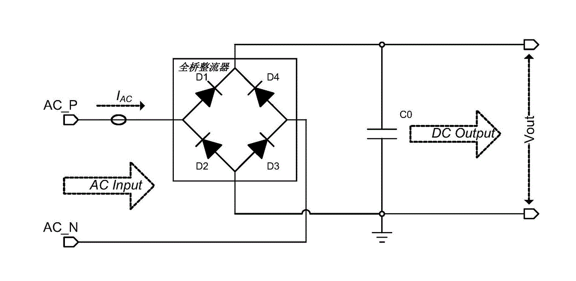
Figure 1: Full Wave Bridge Rectifier Diagram
In this Full Wave Bridge Rectifier Diagram, you can see how the four diodes are arranged in the circuit and how the AC input is converted into a DC output. In the diagram, you will typically see four diodes (D1, D2, D3, D4) arranged in a "bridge" configuration. The AC input is connected across one pair of opposite corners of the bridge, and the DC output is taken from the other pair of corners. During the positive half cycle of the AC input, diodes D1 and D2 are forward-biased (conducting), and diodes D3 and D4 are reverse-biased (not conducting). The current flows through D1, across the load, and then through D2. During the negative half cycle, diodes D3 and D4 are forward-biased, and D1 and D2 are reverse-biased. The current flows through D3, across the load in the same direction as before, and then through D4.
The result is a constant DC output voltage despite the changing polarity of the AC input, which is the primary function of the full wave bridge rectifier.
II. What does a Full Bridge Rectifier do
The main function of a Full Bridge Rectifier is to convert Alternating Current (AC), which oscillates between positive and negative half cycles, into Direct Current (DC) that flows consistently in one direction. AC is the type of current that is supplied to homes and businesses, but most electronic devices require DC for their operation. The Full Bridge Rectifier achieves this conversion through a specific arrangement of four diodes in a bridge circuit. During each half cycle of the AC input, two diodes conduct and allow current to flow through the load, while the other two diodes do not conduct. This mechanism ensures that the direction of the current remains the same during both half cycles, thereby producing a continuous DC output. This ability to convert AC into DC makes Full Bridge Rectifiers a crucial component in many electronic devices and power supplies.
III. How does a Full Bridge Rectifier work
The working principle of the Full Bridge Rectifier circuit is based on the conduction and cutoff control of power switching components. When the positive half cycle of the input AC signal arrives, the controller allows a pair of diodes or MOSFETs to conduct, passing the current from one side of the transformer through the filter capacitor to the output; when the negative half cycle of the input AC signal arrives, the controller allows another pair of diodes or MOSFETs to conduct, likewise passing the current from the other side of the transformer through the filter capacitor to the output.
The main steps of the Full Bridge Rectifier circuit are as follows:
- The input AC signal is reduced through a transformer and provided to four power switching components.
- The controller controls the conduction and cutoff of the two pairs of power switching components based on the positive and negative half cycles of the input AC signal.
- When the positive half cycle of the input AC signal arrives, the controller allows one pair of power switching components to conduct, directing the current from one side of the transformer to the output, completing half bridge rectification.
- When the negative half cycle of the input AC signal arrives, the controller lets the other pair of power switching components conduct, directing the current from the other side of the transformer to the output, completing the other half of the bridge rectification.
- The output voltage is smoothed by a filter capacitor to obtain a stable DC output.
The working principle of the Full Bridge Rectifier circuit allows each power switching component to withstand smaller currents and voltage drops during conduction, thus providing a larger power output. In addition, this circuit also has the advantages of lower harmonic distortion, high efficiency, and better voltage stability.
IV. Advantages and Disadvantages of Full Bridge Rectifier
A. Advantages of Full Bridge Rectifier
- Efficiency: The full bridge rectifier is more efficient than a half-wave rectifier because it utilizes both the positive and negative half cycles of the input AC signal, converting the entire waveform into DC.
- Output: It provides a higher output voltage and a higher output power than a half-wave rectifier.
- Ripple Factor: The ripple factor (a measure of the smoothness of the DC output) is lower in a full bridge rectifier compared to a half-wave rectifier, meaning the output is smoother.
- Transformer Utilization Factor: It has a higher transformer utilization factor than a center-tap rectifier because it uses both halves of the secondary winding.
B.Disadvantages of Full Bridge Rectifier
- Complexity: The circuit design is more complex than that of a half-wave rectifier, requiring four diodes instead of just one.
- Voltage Drop: There is a greater voltage drop due to the use of two diodes in the current path, which reduces the output voltage.
- Diode Requirement: The need for four diodes increases the cost and the size of the rectifier.
- Diode Failure: If one diode fails, the whole circuit will stop functioning.
V. Full Bridge Rectifier vs Bridge Rectifier
Actually, Full Bridge Rectifier and Bridge Rectifier refer to the same kind of circuit. Both terms are used interchangeably in the field of electronics. A Bridge Rectifier or a Full Bridge Rectifier is a kind of rectifier that uses four or more diodes in a bridge arrangement to efficiently convert an Alternating Current (AC) input into a Direct Current (DC) output. It provides full wave rectification, meaning it can convert both the positive and negative half cycles of the AC signal into DC, making it more efficient than a half-wave rectifier. So, there's no difference between a Full Bridge Rectifier and a Bridge Rectifier. They are just different names for the same electronic component.
VI. Full Bridge Rectifier vs Half Bridge Rectifier
The main difference between a Full Bridge Rectifier and a Half Bridge Rectifier lies in their structure and how they convert alternating current (AC) into direct current (DC).
- Full Bridge Rectifier: This configuration uses four diodes arranged in a bridge format. It provides full-wave rectification, meaning it converts both the positive and the negative half cycles of the AC input into DC output. This results in a higher output voltage, higher transformer utilization factor, and smoother output waveform.
- Half Bridge Rectifier: This setup typically involves only two diodes and requires a center-tapped transformer. The half bridge rectifier only rectifies (converts into DC) the positive or the negative half cycle of the AC input, not both. This results in a lower output voltage and a less smooth output waveform compared to a full bridge rectifier.
In summary, a full bridge rectifier is generally more efficient and provides a smoother DC output than a half bridge rectifier. However, the half bridge rectifier can be simpler and cheaper to implement because it requires fewer components.
ALSO READ: Full Bridge Rectifier