A rectifier is an electronic circuit that converts an AC signal into a pulsating DC signal and transforms AC power into DC power. It is used in almost all electronic projects in our daily lives. There are mainly two types of rectifiers: full-wave rectifiers and half-wave rectifiers. This article will primarily introduce full wave rectifier, including its two types , features, and applications.
Rectification and Rectifier
Rectification refers to converting AC alternating current into DC direct current. The polarity of AC changes with frequency, while the polarity and current direction of DC are fixed, hence the term "rectification." A rectifier is the key device that achieves this goal and is an essential component in power systems using AC generators. It typically consists of a set of transistors, diodes, or other semiconductor devices. There are two main variants of rectification technology:
- Full Wave rectifier
- Half Wave Rectifier
What is Full Wave Rectifier
A full-wave rectifier is a circuit device used to convert AC signals into DC signals. By processing the positive and negative half-cycles of the input signal, it makes the output waveform closer to DC. A full-wave rectifier is primarily composed of a diode bridge, which includes four diodes. By operating in different states and conduction modes, it can convert each half-cycle of the AC input signal into a positive DC output signal. As a result, full-wave rectifiers exhibit higher efficiency and output characteristics closer to DC. A full-wave rectifier circuit consists of two power diodes connected to a single load resistor (RL), with each diode alternately supplying current to the load resistor.
What is the Working of Full Wave Rectifier
In a full-wave rectifier circuit using a capacitor filter, the capacitor C is located across the RL load resistor. During the entire positive half-cycle when the input AC voltage is applied, diode D1 gets forward-biased allowing current to flow, while diode D2 gets reverse-biased blocking current flow.
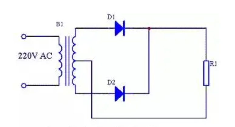
Figure 1: Full Wave Rectifier Circuit diagram
In this half cycle, the current through diode D1 passes through the filter activating the capacitor. However, the capacitor only charges when the applied voltage is higher than the capacitor voltage. Initially, the capacitor does not charge as there is no voltage left between the capacitor plates. Therefore, the capacitor charges immediately when the voltage is applied in the circuit.
Throughout the entire transfer time, the capacitor is charged to the highest value of the supply voltage. The capacitor contains the highest charge at a quarter of the waveform in the positive half-cycle. Eventually, the supply voltage equals the voltage across the capacitor. Once the AC voltage starts decreasing and falls below the capacitor voltage, the capacitor starts discharging gradually.
When the input AC power voltage enters the negative half-cycle, diode D1 gets reverse-biased, but diode D2 gets forward-biased. Throughout the negative half-cycle, the current through diode D2 charges the capacitor through the filter. However, capacitor charging occurs only when the applied AC voltage is higher than the capacitor voltage.
The capacitor in the circuit is not fully charged, so charging does not occur immediately. Once the supply voltage exceeds the capacitor voltage, the capacitor charges. In both half-cycles, the current flows through the RL load resistor in the same direction. Therefore, we either get the entire positive half-cycle or the negative half-cycle. This way, we obtain the total positive half-cycle.
Theory Behind Full Wave Rectifier
In a full-wave rectifier circuit, we use two diodes, with each half-cycle having a diode. Using a multi-tap transformer, its secondary winding is divided into two halves and has a common center tap connection. The configuration of each diode conducting in sequence when its anode terminal is positive relative to the transformer center point C results in output during both half cycles. Compared to a half-wave rectifier, the advantage of a full-wave rectifier is its flexibility.
ALSO READ: Full Wave Rectifier
Full Wave Rectifier Characteristic Formula
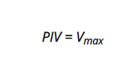
Peak Inverse Voltage (PIV)
Peak Inverse Voltage (PIV) is the maximum voltage that a diode can withstand under reverse bias conditions. If the applied voltage exceeds the PIV, the diode will be damaged. The Peak Inverse Voltage (PIV) can be calculated using the following formula:
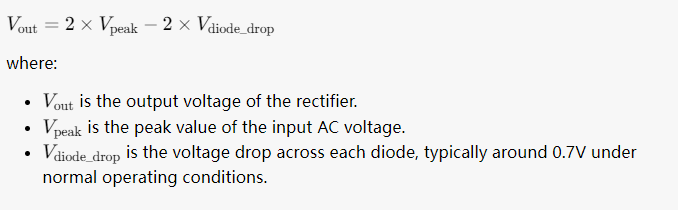
Output Voltage
The calculation formula for the output voltage of a full-wave rectifier depends on the peak value of the input AC voltage (typically represented as Vpeak) and the characteristics of the rectifier circuit. In an ideal full-wave rectifier, the output voltage can be calculated using the following formula:
Average Voltage
A full-wave rectifier utilizes the entire cycle of the electrical signal, generating positive and negative half cycles of AC voltage on the secondary side. Therefore, the ripple factor of the output voltage is smaller than that of a half-wave rectifier, resulting in a more stable output current. The formula for calculating the average voltage of a full-wave rectifier is as follows:
Vdc = 2Vm/π
Where Vdc is the average voltage and Vm is the peak voltage.
Ripple Factor
The size of the ripple factor of a full-wave rectified power supply is related to factors such as input voltage frequency, output filtering capacitor, output load, and the type of rectifier used. Among these factors, the output filtering capacitor is the most significant factor affecting the ripple factor. When the output load increases simultaneously, the ripple factor becomes more apparent. The formula for calculating the power supply ripple factor is as follows:
Vpp = I / (2 * C * f)
Where Vpp is the peak-to-peak ripple value, I is the output current magnitude, C is the output filtering capacitor value, and f is the input AC frequency.
The ripple factor of a full-wave rectified power supply is one of the main factors affecting the quality of the power supply output. A lower ripple factor indicates smaller voltage fluctuations, leading to higher power supply stability. To further reduce the ripple of a full-wave rectified power supply, an appropriately sized filtering capacitor can be added at the output to smooth out the output voltage waveform. By designing and selecting components wisely, the ripple of a full-wave rectified power supply can be effectively reduced, enhancing power supply stability and performance.
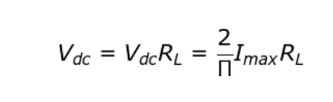
DC Output Current
The direct current output of a full-wave rectifier depends on factors such as the amplitude of the input AC voltage, the value of the load resistance, and the parameters of the components in the circuit. The formula is as follows:
Root Mean Square (RMS) Current
In a full-wave rectifier, the current varies in a sinusoidal waveform, hence its peak value is equal to the maximum value of the current. The RMS current can be calculated using the following formula:
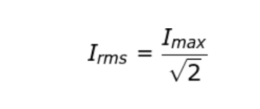
Here, Imax means the peak current.
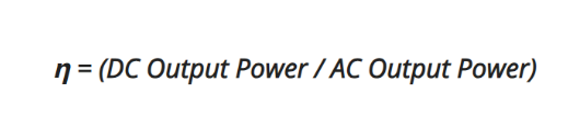
Rectification Efficiency
The rectification efficiency of a full-wave rectifier refers to the energy conversion efficiency between the rectifier's output direct current signal and the input alternating current signal under the input AC signal. The rectification efficiency can be calculated using the following formula:
What are the Types of Full Wave Rectifier
Full-wave rectifiers are essential components in power supply circuits, converting AC voltage into DC voltage. There are primarily two types of full-wave rectifiers: the center-tap transformer-based full-wave rectifier and the bridge rectifier.
- Center Tap Full Wave Rectifier
- Full-Wave Bridge Rectifier
What is Center Tap Full Wave Rectifier
The Center Tap Full Wave Rectifier utilizes a center tap grounded at the secondary end of a transformer, with a diode connected to each end of the transformer output, as shown in the diagram below. The input voltage is coupled through the transformer to the center tap of the secondary end. Half of the total secondary voltage appears across the center tap and the secondary winding at each end.
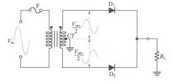
Figure 2: Center Tap Full Wave Rectifier circuit diagram
What is the Working of Center Tap Full Wave Rectifier
During the positive half-cycle of the input voltage, the polarity of the secondary voltage is as shown in figure (a). In this situation, D1 is forward-biased, while D2 is reverse-biased. The current path flows through D1 first and then through the load resistor RL. During the negative half-cycle of the input voltage, the polarity of the secondary voltage is as shown in figure (b). In this case, D1 is reverse-biased, and D2 is forward-biased. The current path flows through D2 first and then through the load resistor RL. Since the output current through the load resistor has the same direction during both positive and negative half-cycles of the input voltage, the output voltage across the load resistor is the DC voltage of the full-wave rectification.
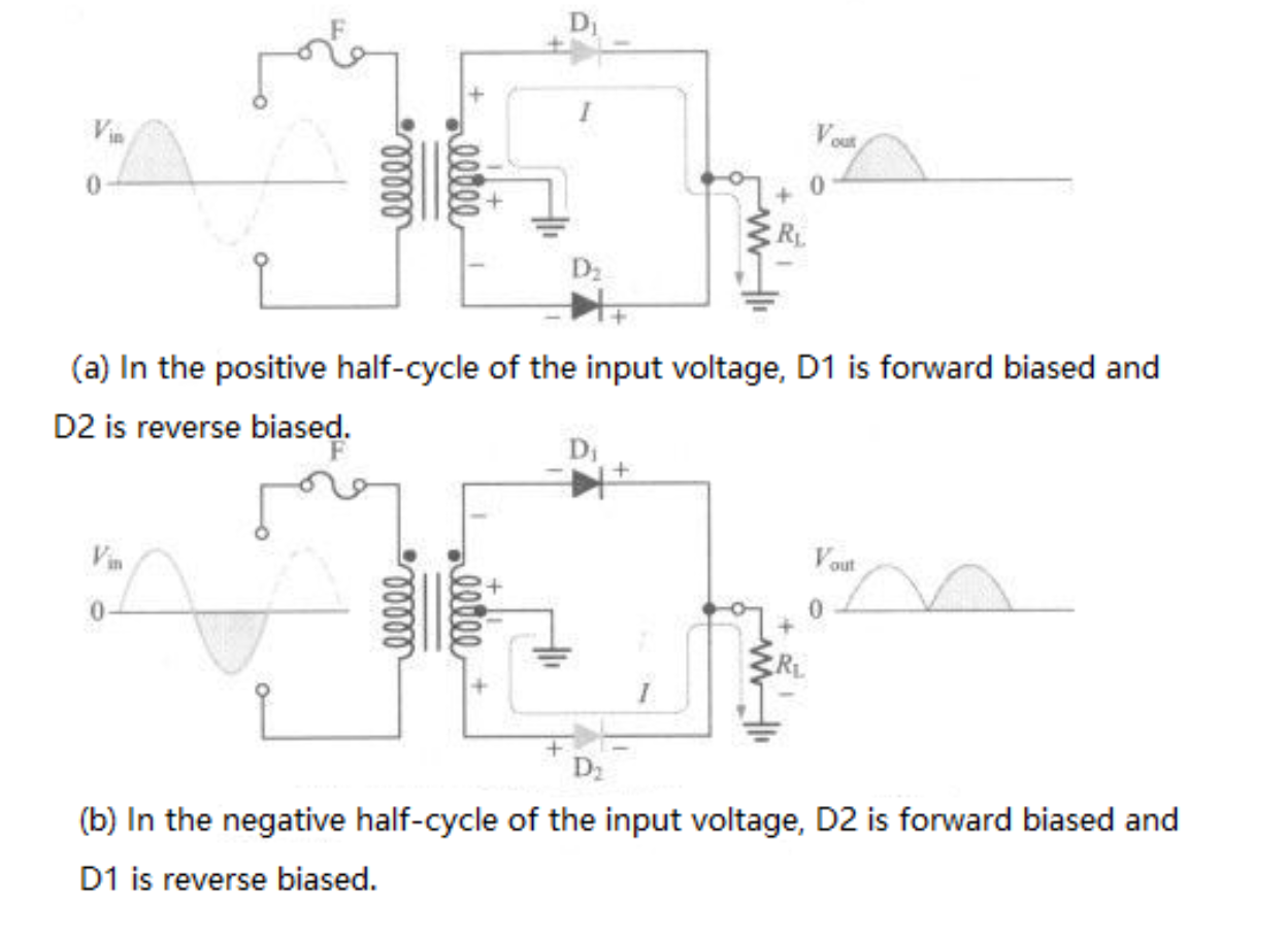
Figure 3: the Working of Center Tap Full Wave Rectifier
What is Full Wave Bridge Rectifier
Compared to a full wave rectifier circuit, a bridge rectifier circuit does not require a center tap on the transformer's secondary winding, but it does necessitate the use of four rectifier diodes. During both the positive and negative half-cycles of the input voltage, two diodes conduct, creating a continuous DC output. The average and RMS output voltage of a bridge rectifier circuit are the same as those of a full wave rectifier circuit, but each diode in the bridge rectifier circuit experiences a lower reverse voltage.
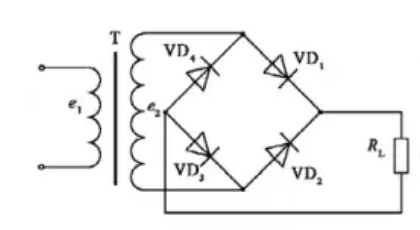 Figure 4: Full Wave Bridge Rectifier circuit diagram
What is the Working of Full Wave Bridge Rectifier
The Full Wave Bridge Rectifier requires the use of four diodes, and the circuit connection is as shown below. As depicted in figure (a), during the positive half-cycle of the input voltage, diodes D1 and D2 are forward-biased, and the direction of current is as shown in the diagram. At this time, the voltage waveform across the load resistor RL is the same as the positive half-cycle of the input voltage. Meanwhile, diodes D3 and D4 are reverse-biased during this period.
As illustrated in figure (b), during the negative half-cycle of the input voltage, diodes D3 and D4 are forward-biased, causing the current direction through the load resistor to align with the direction during the positive half-cycle. During the negative half-cycle of the input voltage, D1 and D2 are reverse-biased. Consequently, the voltage across the load resistor RL becomes the output voltage of the full-wave rectification.

Figure 5: the Working of Full Wave Bridge Rectifier
Full Wave Rectifier vs. Full Wave Bridge Rectifier
Full wave rectifier uses a center-tapped transformer with two diodes to convert alternating current into direct current. It can be seen as a combination of two half-wave rectifier circuits. On the other hand, the Full-Wave Bridge Rectifier eliminates the need for a center-tapped transformer and uses a step-down transformer, four diodes, and a load. In summary, both full wave rectifier and bridge rectifier have the same average and effective output voltage, but differ in circuit structure and diode usage. The key difference lies in their topology and component arrangement. There are their differences:
|
|
Full Wave Rectifier |
Full Wave Bridge Rectifier |
|
Circuit structure |
Full wave Rectifier requires a center-tapped transformer but uses two fewer diodes than the Full-Wave Bridge Rectifier. It rectifies the positive and negative half cycles of the AC signal separately through diodes, resulting in a positive output, thus producing unipolar DC output. |
Full wave bridge rectifier does not require a center tap but employs two additional diodes. Each diode in the bridge rectifier is connected in a scattered manner, where both the positive and negative terminals of each diode are utilized. Half of the AC input cycles pass through each pair of diodes in the bridge, resulting in full bridge rectification output. |
|
ripple |
The output frequency is twice the input frequency, hence the output ripple is relatively large, requiring the use of a filter capacitor to work together to make the output DC more stable. |
The output frequency is the same as the input frequency, so the ripple is relatively small. |
|
applications |
Suitable for low-power devices, such as LED lights, low-voltage DC motors, etc. |
Suitable for high-power devices, such as televisions, computers, audio systems, etc. |
|
Efficiency |
Converting the negative half-cycle of the AC power into a positive half-cycle before rectification leads to some energy loss, resulting in relatively lower efficiency. |
Simultaneously rectifying both the positive and negative half-cycles of the AC power into DC theoretically results in higher efficiency compared to full-wave rectification, leading to lower energy consumption. |
|
Cost |
Low cost, simple structure. A half-wave rectification can be achieved in a full-wave rectifier circuit using only two diodes and a load, making both the cost and structure very simple. |
High cost, complex structure. The structure of a full bridge rectifier requires four diodes and two AC transformers, leading to relatively higher costs. |
|
Stability |
Output voltage fluctuates due to variations in input voltage, resulting in lower stability compared to full bridge rectification. |
Output voltage has minimal fluctuation, ensuring good stability and the ability to meet voltage requirements under various operating conditions. |
|
Reverse Voltage Endurance |
High. The full-wave rectifier circuit requires diodes with double the reverse voltage endurance compared to the bridge rectifier. |
Low. Each diode in a bridge rectifier circuit withstands lower reverse voltage, equivalent to the maximum value of the transformer's secondary voltage. |
Full Wave Rectifier and Full-Wave Bridge Rectifier Applications
- Full wave rectifier: Suitable for applications with low power requirements and small sizes, such as small power supplies for electronic devices. Commonly used in power supplies, battery chargers, motor drives, and LED lighting, typically for low-power applications or constrained spaces.
- Full Wave Bridge Rectifier: Due to its high efficiency and stable DC output, the full-wave bridge rectifier is suitable for a wide range of power requirements, such as high-power supply units, motor drives, and industrial control systems. Widely applied in various electronic devices.
Full Wave Rectifier and Full-Wave Bridge Rectifier Features
- Full wave rectifier: The full-wave rectifier fully utilizes the entire cycle of the AC input, making its efficiency much higher than that of a half-wave rectifier. The output DC voltage and current are relatively large, and since both half-cycles are utilized, the output DC is smoother with lower ripple.
- Full Wave Bridge Rectifier: Compared to a half-wave rectifier, the full-wave bridge rectifier does not require a capacitor filter, offering higher stability and efficiency in the output DC voltage. Additionally, its efficiency is higher than that of a half-wave rectifier because it rectifies both positive and negative half-cycles of the AC signal. Furthermore, the full-wave bridge rectifier does not need a capacitor filter, resulting in a more stable direct output voltage.
Full Wave Rectifier and Full-Wave Bridge Rectifier disadvantages
- Full wave rectifier: The conversion efficiency of a full-wave rectifier circuit is relatively low because only half of the voltage can pass through the load in each half cycle. Additionally, since it uses a single filtering capacitor, the output ripple is higher, which may require further filtering measures to address.
- Full-Wave Bridge Rectifier: Compared to a full wave rectifier, the conversion efficiency of a full-wave bridge rectifier is higher because the voltage of each half cycle can pass through the load. Furthermore, as it employs dual capacitor filtering, it has lower ripple.
Full Wave Rectifier and Full-Wave Bridge Rectifier advantages
- The full wave rectifier, employing a bridge rectifier, has a relatively high conversion efficiency, often exceeding 75%. Additionally, the output DC voltage of a full wave rectifier is stable and only experiences minor variations due to changes in the load or other external disturbances.
- Full Wave Bridge Rectifier: Compared to a full wave rectifier, the conversion efficiency of a full-wave bridge rectifier is higher because the voltage of each half cycle can pass through the load. Furthermore, with the use of dual capacitor filtering, it exhibits lower ripple.
Summary
After comparing the Full Wave Rectifier and Full-Wave Bridge Rectifier, you might wonder, which is better between a full wave rectifier and a Full-Wave Bridge Rectifier? This actually depends on the specific application scenarios and requirements. If you have constraints on cost and circuit complexity, then full-wave rectification is a good choice. If you need higher conversion efficiency and lower ripple, then a full-wave bridge rectifier should be selected. However, it's important to note that the full-wave bridge rectifier has higher costs and requires additional capacitors to suppress ripple, so in some cases, this might not be the optimal choice.
ALSO READ: How to Test Capacitor with Multimeter
Full Wave Rectifier vs. Half Wave Rectifier
|
|
Full Wave Rectifier |
Half Wave Rectifier
|
|
circuits |
Utilize four bridge rectifiers or a center-tapped transformer with two diodes to convert each half cycle of AC into DC. |
Use a single diode to allow one half cycle of AC to pass through while blocking the other half cycle. |
|
Manufacturing Cost |
relatively high. |
circuit is simple and cost-effective. |
|
Applications |
Widely used in high-power circuits. |
Output voltage fluctuates significantly, suitable only for certain low-power circuits. |
|
Operating Principle |
output voltage in both positive and negative half cycles. |
only output voltage in the positive (or negative) half cycle. |
|
Output Voltage |
The output voltage is the full amplitude of the input waveform. |
The output voltage is half the amplitude of the input waveform. |
|
Output Ripple |
The output voltage ripple is small in a full-wave rectifier, making it more stable compared to a half-wave rectifier. |
The output voltage ripple is large and requires smoothing through a filtering circuit. |
|
Efficiency |
High efficiency as it can utilize the full power of the input signal. |
Low efficiency as only half of the AC signal is utilized. |
You might ask, which is better between a full-wave rectifier and a half-wave rectifier? This depends on your specific application requirements. For cost-sensitive and low-power needs in small devices, a half-wave rectifier is a more economical choice. For applications requiring stable and efficient DC power, a full-wave rectifier is the better option.
FAQs
How many diodes are used in full wave rectifier
In a full-wave rectifier, typically four diodes are used, arranged in a bridge configuration.
Which diode is used in full wave rectifier
Commonly, general-purpose silicon diodes like 1N4007 are used in full-wave rectifiers due to their high current and voltage ratings.
What is the output frequency of full wave rectifier
The output frequency of a full-wave rectifier is twice the input frequency, as it rectifies both halves of the AC cycle.
Why we use center tapped transformer in full wave rectifier
A center-tapped transformer is used in a full-wave rectifier to create two out-of-phase voltages, allowing both halves of the AC cycle to be rectified.
What is ripple factor of full wave rectifier
The ripple factor of a full-wave rectifier is typically around 0.482, indicating lower ripple compared to half-wave rectifiers.