Overview: This technical piece shows how the three-phase inverter works in the 120-degree conduction mode. To make things easier to understand, the six thyristors' functions and the patterns that go with them are shown.
Three-phase transformers are mostly used for tasks that need medium to high power. These days, three-phase inverters are used to precisely control things like motor drives, solar power plants, and industrial drives. One can also control the power and frequency with these inverters, among other things.
As seen in Figure 1, the three-phase inverters use at least six thyristor switches. From a direct current (DC) input, this type of power electronics converter creates a three-phase alternating current (AC) output.
Figure 1. Circuit diagram of a three phase inverter. Image used courtesy of Rakesh Kumar, Ph.D.
It has three legs, and two thyristors are on each leg. The thyristors in the lower leg are numbered even, while the ones in the upper leg are numbered odd. The load that is linked in a star connected is tapped in the middle of each leg, where the two thyristors meet.
Three Phase Inverter Operatation in 120 Degree Conduction Mode
Different thyristors' transmission periods are shown in Figure 2 for each 60-degree part of the full 360-degree cycle. And so, there are six ways to use it. Each thyristor can be seen to conduct for 2*60 degrees, which is 120 degrees all the time.
Each leg's pair of thyristors is 180 degrees out of phase with the other pair. In other words, there is only one thyristor on in each leg at any given time. Another thing that can be seen is that each thyristor is 120 degrees out of phase with the thyristor next to it on the next leg.
Figure 2. Operating periods of the thyristors for every 60 degree in 120 degree conduction mode of three phase inverter. Image used courtesy of Rakesh Kumar, Ph.D.
Operating Mode 1 - 0 to 60 Degree [M1]
Mode 1 corresponds to a 0 to 60 degree period. During this period, the thyristors T1, and T6 are turned on. This can be seen in Figure 3.
On the load side, the current enters phase a and leaves via phase b. The equivalent circuit diagram of the same is placed on the right side of Figure 3.
On applying the voltage division rule, the phase-to-neutral voltages are as follows:
Van = Vin/2 (1)
Vbn = -Vin/2 (2)
Vcn = 0 (3)
The phase-to-phase voltages are as follows:
Vab = Van - Vbn = Vin (4)
Vbc = Vbn - Vcn = -Vin/2 (5)
Vca = Vcn - Van = -Vin/2 (6)
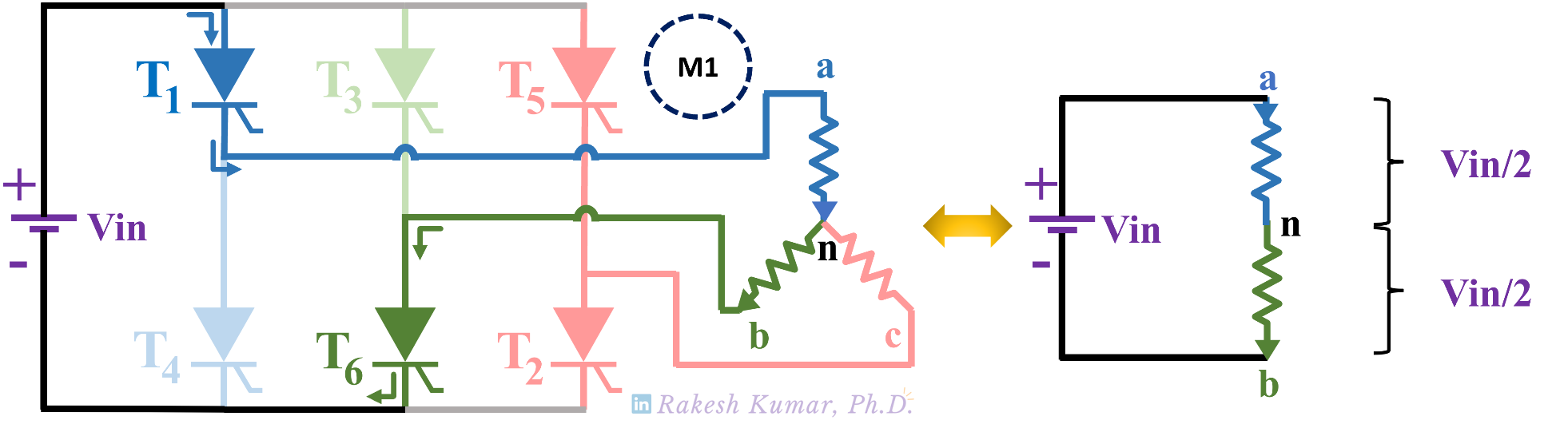
Figure 3. Mode 1 operation of a three phase inverter in 120 degree conduction mode. Image used courtesy of Rakesh Kumar, Ph.D.
Operating Mode 2 - 60 to 120 Degree [M2]
Mode 2 corresponds to a 60 to 120 degree period. During this period, the thyristors T1, and T2 are turned on. This can be seen in Figure 4.
On the load side, the current enters phase a and leaves via phase c. The equivalent circuit diagram of the same is placed on the right side of Figure 4.
On applying the voltage division rule, the phase-to-neutral voltages are as follows:
Van = Vin/2 (7)
Vbn = 0 (8)
Vcn = -Vin/2 (9)
The phase-to-phase voltages are as follows:
Vab = Van - Vbn = Vin/2 (10)
Vbc = Vbn - Vcn = Vin/2 (11)
Vca = Vcn - Van = -Vin (12)
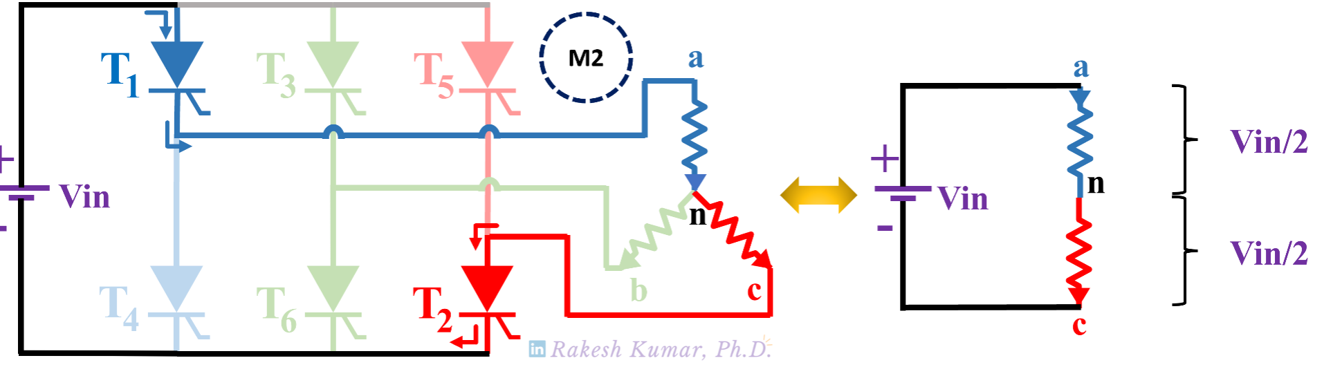
Figure 4. Mode 2 operation of a three phase inverter in 120 degree conduction mode. Image used courtesy of Rakesh Kumar, Ph.D.
Operating Mode 3 - 120 to 180 Degree [M3]
Mode 3 corresponds to a 120 to 180 degree period. During this period, the thyristors T2, and T3 are turned on. This can be seen in Figure 5.
On the load side, the current enters phase b and leaves via phase c. The equivalent circuit diagram of the same is placed on the right side of Figure 5.
On applying the voltage division rule, the phase-to-neutral voltages are as follows:
Van = 0 (13)
Vbn = Vin/2 (14)
Vcn = -Vin/2 (15)
The phase-to-phase voltages are as follows:
Vab = Van - Vbn = -Vin/2 (16)
Vbc = Vbn - Vcn = Vin (17)
Vca = Vcn - Van = -Vin/2 (18)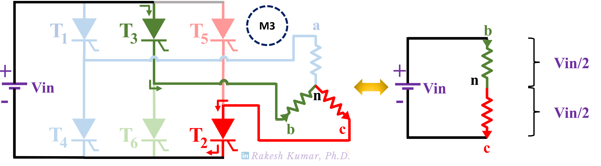
Figure 5. Mode 3 operation of a three phase inverter in 120 degree conduction mode. Image used courtesy of Rakesh Kumar, Ph.D.
Operating Mode 4 - 180 to 240 Degree [M4]
Mode 4 corresponds to a 180 to 240 degree period. During this period, the thyristors T3, and T4 are turned on. This can be seen in Figure 6.
On the load side, the current enters phase b and leaves via phase c. The equivalent circuit diagram of the same is placed on the right side of Figure 6.
On applying the voltage division rule, the phase-to-neutral voltages are as follows:
Van = -Vin/2 (19)
Vbn = Vin/2 (20)
Vcn = 0 (21)
The phase-to-phase voltages are as follows:
Vab = Van - Vbn = -Vin (22)
Vbc = Vbn - Vcn = Vin/2 (23)
Vca = Vcn - Van = Vin/2 (24)
Figure 6. Mode 4 operation of a three phase inverter in 120 degree conduction mode. Image used courtesy of Rakesh Kumar, Ph.D
Operating Mode 5 - 240 to 300 Degree [M5]
Mode 5 corresponds to a 240 to 300 degree period. During this period, the thyristors T4, and T5 are turned on. This can be seen in Figure 7.
On the load side, the current enters phase c leaves via phase a. The equivalent circuit diagram of the same is placed on the right side of Figure 7.
On applying the voltage division rule, the phase-to-neutral voltages are as follows:
Van = -Vin/2 (25)
Vbn = 0 (26)
Vcn = Vin/2 (27)
The phase-to-phase voltages are as follows:
Vab = Van - Vbn = -Vin/2 (28)
Vbc = Vbn - Vcn = -Vin/2 (29)
Vca = Vcn - Van = Vin (30)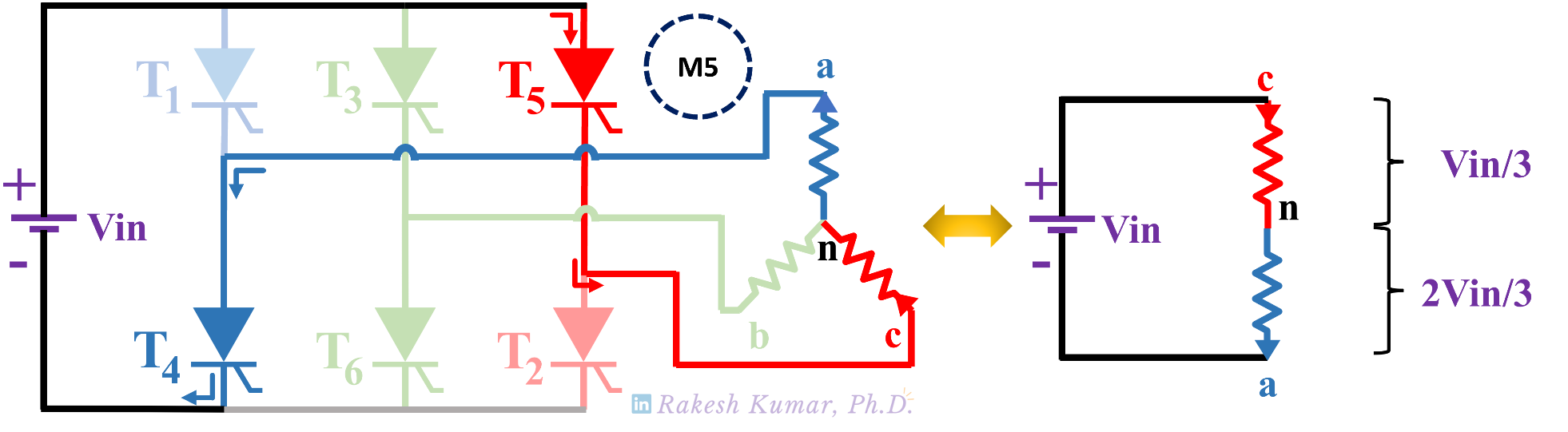
Figure 7. Mode 5 operation of a three phase inverter in 120 degree conduction mode. Image used courtesy of Rakesh Kumar, Ph.D.
Operating Mode 6 - 300 to 360 Degree [M6]
Mode 6 corresponds to a 300 to 360 degree period. During this period, the thyristors T5, and T6 are turned on. This can be seen in Figure 8.
On the load side, the current enters phase c and leaves via phase b. The equivalent circuit diagram of the same is placed on the right side of Figure 8.
On applying the voltage division rule, the phase-to-neutral voltages are as follows:
Van = 0 (31)
Vbn = -Vin/2 (32)
Vcn = Vin/2 (33)
The phase-to-phase voltages are as follows:
Vab = Van - Vbn = Vin/2 (34)
Vbc = Vbn - Vcn = -Vin (35)
Vca = Vcn - Van = Vin/2 (36)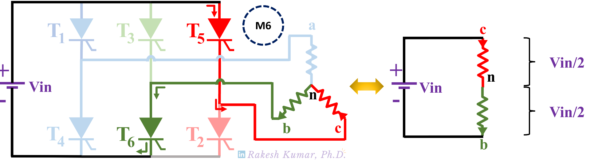
Figure 8. Mode 6 operation of a three phase inverter in 120 degree conduction mode. Image used courtesy of Rakesh Kumar, Ph.D.
Output Phase-to-Neutral Voltage Waveforms of the Three Phase Inverter
Figure 9 shows the load phase-to-neutral voltage waveforms for a single cycle (360 degree). It can be observed that an individual phase-to-phase voltage waveform is continuous for 120 degree, followed by a zero voltage.
The other observation is that each of the phase-to-neutral voltage waveforms is phase shifted by 120 degree. All three waveforms put together assume a three phase output.
Figure 9. Phase-to-neutral waveforms of three phase inverter under 120 degree conduction mode. Image used courtesy of Rakesh Kumar, Ph.D.
Output Phase-to-Phase Voltage Waveforms of the Three Phase Inverter
Figure 10 shows the load phase-to-phase voltage waveforms for a single cycle (360 degree). It can be observed that an individual phase-to-neutral voltage waveform varies in steps during each 60 degree phase.
The other observation is that each of the phase-to-phase voltage waveforms is also phase shifted by 120 degree, just like the phase-to-neutral voltage waveform.
Figure 10. Phase-to-phase waveforms of a three phase inverter in 120 degree conduction mode. Image used courtesy of Rakesh Kumar, Ph.D.
If you want to see the whole piece in one picture, look at Figure 11. It shows all six modes of operation as an animated GIF.