Noise is a common part of circuits as different components, frequencies and currents interact with each other or near each other. In complex circuits, various combinations of direct, low frequency, high frequency, audio frequency and radio frequencies might exist. Therefore, it is necessary to have ways of separating the currents to make use of the desired. To attenuate and pass the required frequencies within a circuit it is necessary to introduce filters in the circuit.
Filtering is used in a wide range of signal-processing applications, from communication and semiconductors to power systems. In this article, we explore the various types of filters and how they work.
Let’s have a look.
WHAT IS A FILTER?
Filters are used in circuits to remove (pass) some frequencies whilst also blocking (attenuating) unwanted frequencies in the circuit. Filters are usually circuits used in noisy circuits to remove unwanted or irrelevant frequencies.
A filter circuit is made of a combination of resistors (R), inductors (L) and capacitors (C). It can either be a combination of these components or a singular component depending on the desired output. The filtering effect is based on the basic operating principle of the components. When used as a filter, a capacitor (C) passes all alternating current while blocking all direct current, thus effectively separating AC from DC. Inductor (L), allows for direct currents to pass while opposing alternating current. On the other hand, resistance (R) on its own does not provide any filtering but when used in combination with inductance or capacitance it provides filtering to a wider band of frequencies.
For example, ideally, a rectifier is expected to produce pure D.C supply to have ideal results in the circuit it is used. In practice, this is not the case as the rectifier produces a pulsating D.C output, meaning it contains both D.C and A.C components. This is not desirable as the pulsating would introduce noise in the circuit. To attenuate the undesired noise, a filter circuit is used to remove the A.C components, allowing only the D.C.
TYPES OF FILTERS
There are four major types of filters with respect to relative values of the cut-off frequency. These include low-pass filters, high-pass filters, band-pass filters and the notch filter.
Low Pass Filter
A Low-pass filter allows a majority of the signals with a frequency lower than a cut-off threshold while attenuating frequencies beyond this point. Sometimes it is called a high-frequency attenuator or discriminator.
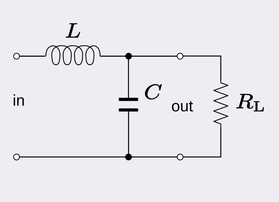
Figure 1: Low Pass Filter
High Pass Filter
A high-pass filter permits frequencies above a specified cut-off while suppressing those below the cut-off frequency before it passes on to the next circuit. Sometimes this filter is called a low-frequency attenuator.
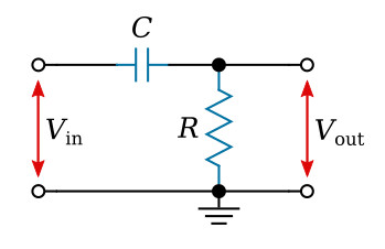
Figure 2: High Pass Filter
Band Pass Filter
A band-pass filter merges the characteristics of low-pass and high-pass filters within a single filtering device.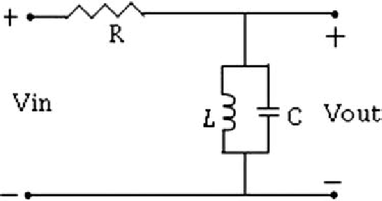
Figure 3: Band Pass Filter
Notch (Band Reject) Filter
A notch (or band-stop) filter transmits all frequencies except those falling within a predetermined range determined by the filter's component values.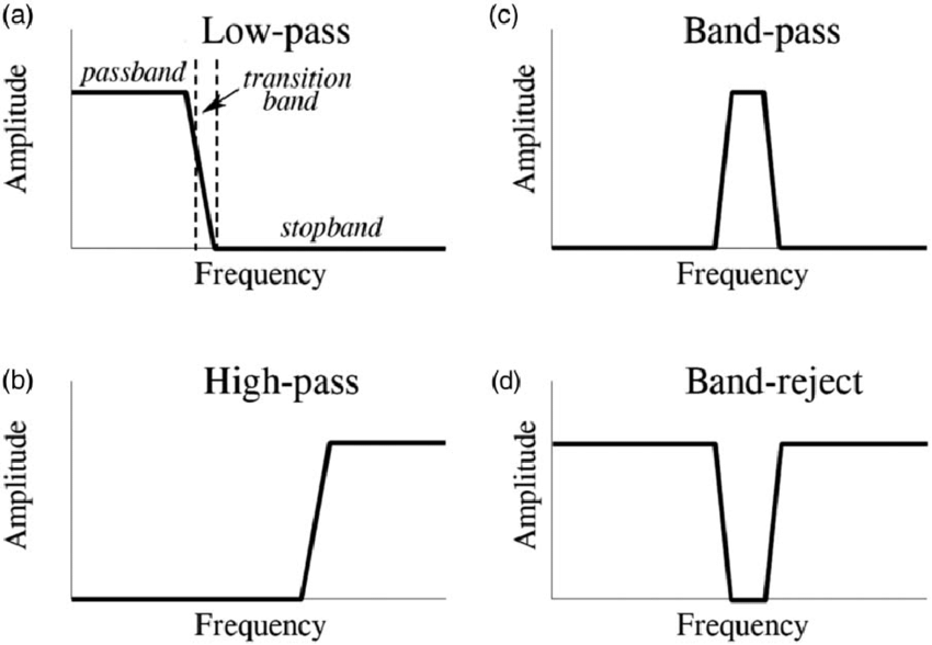
Figure 4 Filter Circuit Curves
ACTIVE FILTERS AND PASSIVE FILTERS
Apart from classifying the filters with respect to the relative values of the cut of frequency, a filter can also be differentiated based if they are passive or active circuits.
Passive Filters
Passive filters are electronic circuits that operate without the use of an external power source. To filter and shape signals, they generally employ passive components such as resistors, capacitors, and inductors. Passive filters are suitable for low-frequency applications because they are simpler and less complex than active filters. The passive filter operates optimally within frequencies between 100 Hz- 300 MHz (with modification the limit can be extended). Low-pass, high-pass, band-pass, and band-stop (notch) filters are examples of common passive filter types.
Active Filters
Active filters, on the other hand, rely on active components such as operational amplifiers (op-amps) and transistors as well as passive components. Active filters do not include inductors, they are designed with resistors and capacitors. These filters require an external power supply to operate and can handle a broader frequency range, making them useful for both low and high-frequency applications. Active filters provide greater control and flexibility in modifying the frequency response and, in addition to filtering, can provide amplification. This makes them capable of dealing with very low frequencies, approaching 0 Hz. When more complex or exact filtering is necessary, they are frequently used.
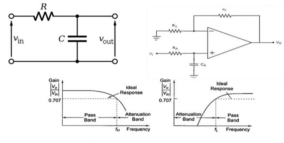
Figure 5 Active vs Passive Filter
Applications of Filter Circuits
It is clear that filter circuits are paramount to electronic components and circuits. As such in the field of electronics, filter circuits have a wide range of applications in electronics and signal processing to modify or shape the frequency characteristics of signals.
Here are a few applications:
Radio Frequency and Communication
Filters are mostly known for their use in radio frequency and communication in bandwidth control. These circuits are employed by radio receivers to isolate specific signals while attenuating unwanted signals. Thus, facilitating fine tuning to the desired frequency and isolating noise from the signal.
On the other hand, in transmission, circuit filters are used to both separate and combine multiple signals to allow for simultaneous transmissions and reception of the same transmission on different frequencies.
Audio Processing
Filter circuits play a crucial role in sound systems and sound processing. Sound is a mixture of frequencies, often some desirable and others undesirable. The filter circuits are used for equalization; enhancement or suppression of specific frequencies to ensure quality audio. In hi-res quality audio, a crossover network, type of filter circuit is used in dividing audio signals into distinct frequency bands that can be directed into appropriate speakers in music systems.
For better audio quality filter circuits are used to reduce noise. They are used to filter out and eliminate unwanted background noise and interference for quality output.
Power Supply
Direct Current power supply requires filtering circuits to improve the stability of DC output. Without filtering circuits, DC power supplies would be noisy and cause humming due to AC and DC currents.
Ripple filtering circuits ensure that DC power supplies deliver a constant and smooth voltage by minimizing fluctuations, essential for the reliable operation of electronic devices.
Furthermore, noise reduction filters are employed to remove high-frequency disturbances from power lines, ensuring that sensitive equipment receives clean and uninterrupted power.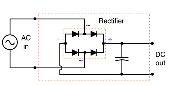
Figure 6: DC Power Supply with a Filter
Medical Equipment
Filter circuits are used in electrocardiography (ECG) in the area of medical electronics to filter and amplify cardiac impulses, providing crucial information to healthcare professionals. To accurately process and analyse data, pulse oximetry, which is used to assess oxygen levels in the blood, relies on filter circuits.
Final Thoughts
Filter circuits are used in medical electronics to filter and enhance heart signals, providing crucial information to healthcare experts. To process and analyse data effectively, pulse oximetry, which is used to assess oxygen levels in the blood, relies on filter circuits.


