Capacitance and capacitor impedance are two very important concepts in electronics and electrical engineering.
Capacitance is a measure of a capacitor's ability to store charge. It is measured in Farads (F), defined as the number of Coulombs (C) stored per Volt (V). A capacitor with a high capacitance can store more charge at the same voltage.
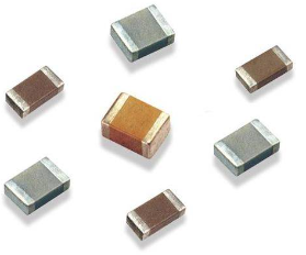 Figure 1: capacitance
Impedance of capacitor, on the other hand, is the degree to which a capacitor impedes the flow of current in an alternating current (AC) circuit. The size of the impedance is related to the capacitance and the frequency of the AC. Unlike resistance, impedance does not consume electrical energy and convert it into heat energy, but stores and releases electrical energy in the capacitor.
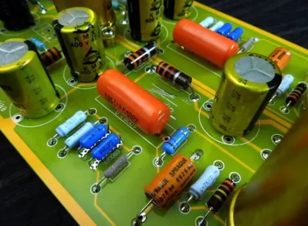
Figure 2: Impedance of capacitor
In AC circuits, the impedance of a capacitor decreases as the frequency increases. This means that capacitors impede the current less at high frequencies. This is because the capacitor can charge and discharge faster in each AC cycle. This characteristic makes capacitors have many applications in power systems and electronic devices, such as filtering, coupling, and decoupling.
Understanding Impedance of Capacitor
Impedance of capacitor
In circuits with capacitance, the impedance created by the capacitor is the opposition to the current in the circuit. Impedance, often represented by Z, is a complex number, the real part of which is called resistance, and the imaginary part is called reactance. Specifically, the opposition caused by the capacitor in the circuit to alternating current is called capacitive reactance, and the opposition caused by the inductor in the circuit to alternating current is called inductive reactance. The overall opposition caused by capacitors and inductors in the circuit to alternating current is collectively referred to as reactance. The unit of impedance is ohms. The concept of impedance not only exists in circuits, but also involves vibrational systems in mechanics. Impedance is the vector sum of resistance and reactance.
Impedance in AC Circuits
Impedance is the active resistance of a circuit or component to alternating current, evolved from the combined effects of reactance and ohmic resistance. In other words, impedance is simply an extension of the principle of resistance in AC circuits. We also define it as any obstacle or measurement of the resistance to the flow of current and energy when a voltage is applied.
A more professional definition is the resistance offered by a circuit to the flow of alternating current at a single frequency. In summary, it is the combination of reactance and resistance that we measure in ohms, represented by the symbol Z.
However, reactance (X) represents the resistance of a component to AC, while impedance (Z) is the sum of resistance and reactance. We use the following formula to display it as a complex number:
 Figure 3: impedance of capacitor formula
In this case, the complex impedance is Z.
We represent resistance as R (real aspect).
We represent reactance as X (imaginary aspect).
It's worth noting that reactance can be negative or positive, while resistance is always positive. Moreover, reactance stores energy in a magnetic field or electric field, whereas resistance in a circuit dissipates power as heat.
Now that we have discussed impedance in AC circuits, let's take a look at how to calculate the impedance of a capacitor.
How to Calculate the Impedance of a Capacitor
A capacitor introduces a certain level of capacitance into the circuit. Functionally, a capacitor provides temporary electrical energy storage in the form of potential, where the current of the capacitor leads its voltage by 90°. The formula for capacitive impedance is as follows:
XC is the capacitive reactance, which represents the resistance value of the capacitor at a specific frequency. The above formula can be further expanded as follows:
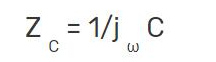
Here, the impedance of the capacitor is ZC. The angular frequency is ω, which we calculate as:
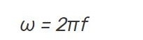
We represent the frequency of the signal as f, and the capacitance of the capacitor as C.
In terms of capacitor parameters, the resistance of an ideal capacitor is zero. However, the reactance and impedance of a real capacitor are negative for all capacitance and frequency values. The effective impedance (absolute value) of a capacitor depends on the frequency and decreases with the frequency.
From the above equations, it is clear that the reactance of a capacitor is inversely proportional to the capacitance and frequency. Therefore, higher capacitance and higher frequency translate into lower reactance. This allows capacitors to be used with other components in the design of low-pass or high-pass filters, and to block selective frequencies.
Differences between Impedance of capacitor and inductor
Impedance, in the context of AC circuits, is the measure of opposition that a circuit presents to the current when a voltage is applied. The impedance of both capacitors and inductors is frequency-dependent, but they behave differently due to their unique properties.
For a Capacitor:
The impedance (Z) of a capacitor is given by the formula Z = 1/(jωC), where j is the imaginary unit, ω is the angular frequency, and C is the capacitance. This is also known as capacitive reactance. Capacitive reactance decreases with the increase in frequency. This means that capacitors offer high impedance to low-frequency signals and low impedance to high-frequency signals.
For an Inductor:
The impedance (Z) of an inductor is given by the formula Z = jωL, where L is the inductance. This is known as inductive reactance. Unlike capacitors, inductive reactance increases with the increase in frequency. This means that inductors offer low impedance to low-frequency signals and high impedance to high-frequency signals.
In summary, capacitors and inductors have opposite behaviors when it comes to impedance. Capacitors resist changes in voltage (they "oppose" high frequencies), while inductors resist changes in current (they "oppose" low frequencies).
From Capacitance to Impedance
The process of converting capacitance to impedance
There are capacitive reactance calculators that allow you to determine the impedance of a capacitor as long as you have the capacitance value (C) of the capacitor and the frequency of the signal passing through the capacitor (f). You can input the capacitance in farads, picofarads, microfarads, or nanofarads, and the frequency in GHz, MHz, kHz, or Hz. For example, a capacitance of 2 farads at a frequency of 100 hertz will produce an impedance of 0.0008 ohms.
Here is the formula needed to calculate the above values:
Z = 1 / (jωC)
In this equation:
Z is the impedance of the capacitor, expressed in ohms.
j is the unit of imaginary numbers, equal to the square root of -1.
ω is the angular frequency of the AC, equal to 2π times the frequency f (in hertz).
C is the capacitance of the capacitor, in farads.
This equation tells us that the impedance of the capacitor is a function of frequency and capacitance. Specifically, the impedance of a capacitor decreases as the frequency increases, and increases as the capacitance increases.
It's worth noting that this impedance equation actually describes the reactance of the capacitor (i.e., capacitive reactance). In an ideal capacitor, the resistance is zero, so the reactance is equal to the impedance. But in a real capacitor, there may also be some resistance, so the impedance needs to consider the combined effects of resistance and reactance.
Now, we understand the parameters of ideal resistance, that is, its impedance equals its resistance. However, although these two parameters are not the same, the impedance of an ideal capacitor is equal to the magnitude of its reactance. We represent reactance as a regular number in ohms, and the impedance of a capacitor is the value obtained by multiplying the reactance by -j. This is related to the following formula:
Z = -jX
In this case, the -j term represents the 90-degree phase shift that occurs between current and voltage in a purely capacitive circuit.
Examples
Suppose we have a capacitor with a capacitance of 0.001 Farads (F) and an alternating current frequency of 60 Hertz (Hz). We can use the impedance formula to calculate the impedance.
First, we need to convert the frequency to angular frequency, ω = 2πf = 2π*60 ≈ 377 radians/second. Then, we substitute the angular frequency and the capacitance into the impedance formula to get Z = 1 / (jωC) = 1 / (j*377*0.001) ≈ -j2677 ohms.
Note that the result is a negative imaginary number, which indicates that the current in the capacitor leads the voltage by 90 degrees, a typical characteristic of capacitors in AC circuits.
Comparing reactance and impedance
Reactance and impedance are two key elements in the study of alternating current (AC) circuits.
Reactance is a measure of how a capacitor or inductor opposes the change in electrical current in an AC circuit. It is frequency-dependent, meaning its value varies with the frequency of the AC signal. Reactance can be either capacitive (when caused by a capacitor) or inductive (when caused by an inductor). Capacitive reactance decreases with increasing frequency, while inductive reactance increases with increasing frequency.
Impedance, on the other hand, is a broader term that describes the total opposition to electrical current in an AC circuit. It is a combination of resistance (which occurs in all types of circuits, both DC and AC) and reactance. Unlike resistance, which is a real number, impedance is a complex number that can have both magnitude and phase. The magnitude of impedance gives the ratio of the voltage amplitude to the current amplitude, and the phase gives the phase difference between the voltage and the current.
In simple terms, reactance is one component of impedance, specifically the component that is caused by capacitors and inductors. Impedance, on the other hand, is the total opposition to current, including both the effects of resistance and reactance.
Applications
The concept of capacitive impedance is very important in many electronic and electrical engineering applications. For example, in radio frequency and microwave systems, impedance matching is a key design principle that can ensure maximum power transmission and reduce reflections.
Another example is the system of alternating current power supplies and motors. In these systems, capacitors and inductors are often used to adjust the power factor of the power supply to improve system efficiency. This requires understanding and calculating the impedance of capacitors and inductors.
In audio electronic equipment, such as speakers and sound systems, the impedance of capacitors and inductors will also affect the frequency response of the equipment, thereby affecting the sound quality.
In general, understanding and calculating capacitive impedance is a basic skill in electronics and electrical engineering.
Here is a useful video to help you understand deeper about the impedance and capacitance of a capacitor.
Capacitive Reactance, Impedance, Power Factor, AC Circuits, Physics