Introduction
What is a Capacitor
A capacitor is an important electrical component. It is made by putting an insulating material -- a dielectric (air can also act as a dielectric) between two closely spaced parallel metal plates, forming the simplest form of a capacitor, known as a parallel plate capacitor. These two metal plates are called the plates of the capacitor. In fact, any two conductors that are insulated from each other and are close to each other can be considered a capacitor. Capacitors are one of the most widely used electronic components in electronic devices, and are widely used in circuits for DC isolation, AC coupling, bypassing, filtering, tuning circuits, energy conversion, control, and other aspects.
What is a Multimeter
A multimeter is a portable electronic testing instrument used to measure physical quantities such as voltage, current, and resistance in circuits. It is one of the most commonly used tools in the field of electronics, and is widely used in the maintenance of electronic equipment, circuit design, and experiments.
Multimeters usually consist of a digital display, a selection dial, test leads, and measurement ports. They can measure direct current voltage (DCV), alternating current voltage (ACV), direct current (DCA), alternating current (ACA), resistance (Ω), and other additional functions, such as capacitance, frequency, temperature, etc. By selecting the corresponding measurement range through the dial and connecting the test leads to the circuit under test, the multimeter displays the measurement results in digital form on the screen, making it convenient for users to read and analyze.
Before using a multimeter, you first need to determine whether your measurement target is voltage, current, or resistance. When reading the measurement value on the screen of the multimeter, be sure to pay attention to the unit, which may be volts (indicating voltage), amperes (indicating current), or ohms (indicating resistance). If you are unsure of the size of the value you are going to measure, you should first set the multimeter to the highest value in your expected range, which can prevent damage to the multimeter due to overload.
Recognizing Capacitor Symbols
Detailed Description of Capacitor Symbols
In circuit diagrams, the symbol for a capacitor is usually represented as two parallel lines or one straight line and one curved line. These two lines represent the two electrodes (or "plates") inside the capacitor, and the space between the two electrodes (the gap between the lines in the symbol) represents the dielectric, which is the non-conductive material between the electrodes. The symbols for capacitors are often represented by C, CN, TC or BC.
There are many kinds of capacitors with different functions. Different types of capacitors have different circuit graphic symbols and text representations, such as non-polar capacitors, electrolytic capacitor and ariable capacitorand polar capacitors each have their circuit graphic symbols. These symbols help electronics engineers identify the various parts of a circuit and their functions when designing and understanding it, and their graphical symbols in the circuit are shown in the following figure:
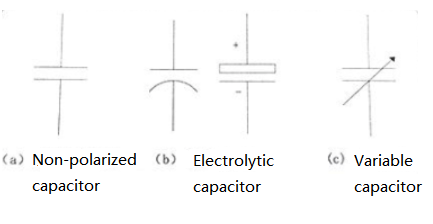 Figure: The circuit graphic symbols of different capacitors
How to find the capacitor symbol on the multimeter
To find the capacitor symbol on a multimeter, you first need to determine whether your multimeter has the function of measuring capacitance. Not all multimeters have this feature, but many modern digital multimeters (DMM) can measure capacitance.
Capacitance is measured in farads, usually in microfarads (uF), nanofarads (nF), or pitofarads (pF). On multimeters, the symbol for the capacitor is usually a symbol similar to the letter "F" or a simple graph of the capacitor represented by a wire frame.
Here are the steps to find the capacitor symbol:
- View the knob or button of the multimeter. If your multimeter can measure capacitance, there should be a symbol or label indicating capacitance on the knob or button.
- Find the symbol for capacitance. This is usually a letter "F", or a simple graphic of a capacitor.
- Turn the knob to this symbol, and your multimeter is now set to measure capacitance mode.
Please note that different models of multimeters may vary, so it is best to consult your multimeter's owner's manual for specific instructions.
How to use a multimeter to measure capacitors
To measure capacitors with a multimeter, follow these steps:
- Make sure your multimeter has the capability to measure capacitance: Not all multimeters have this capability, but many modern multimeters (especially digital multimeters) can measure capacitance.
- Power off: Before measuring the capacitor, be sure that the capacitor has no voltage, as voltage may damage the multimeter.
- Discharge capacitor: For safety, ensure that the capacitor has been fully discharged. Discharge can be done by connecting the resistor to both ends of the capacitor, or if you determine that the capacitor has no voltage in the circuit, you can directly short the capacitor ends.
- Set the multimeter: Turn the knob of the multimeter to the gear for measuring the capacitance (usually represented by an "F" or a symbol for the capacitor).
- Connect the multimeter to the capacitor: Connect the red (positive) probe of the multimeter to the positive electrode of the capacitor (if any), and the black (negative) probe to the negative electrode of the capacitor.
- Read data: On the display of the multimeter, you can see the capacitance value of the capacitor. The units of attention may be microfa (uF), Nanofa (nF), or Picfa (pF).
- Disconnect: After recording the reading, disconnect the multimeter from the capacitor.
Note: Be careful when handling capacitors, as electrical energy may be stored inside the capacitor even if the power supply is disconnected.
Problems that may be encountered when measuring capacitors with multimeters
When using a multimeter to measure capacitors, you may encounter the following common problems:
- The capacitor is not fully discharged: Before measuring the capacitor, it should be ensured that the capacitor is fully discharged. Otherwise, the multimeter may become damaged or display inaccurate readings.
- Capacitance value out of the measuring range: If the capacitance value of the capacitor exceeds the measuring range of the multimeter, the multimeter may not be able to give an accurate reading. In this case, you need to use a device with a larger measuring range.
- Capacitor damage: If the capacitor is damaged or aged, it may not work properly, resulting in a multimeter that cannot measure an accurate capacitance value.
- Reverse connection of polar capacitors by mistake: For polar capacitors (such as electrolytic capacitors), the connection of positive and negative electrodes is very important. If the capacitor is reversed, it may cause damage to the capacitor and also cause inaccurate readings.
- The multimeter is not set correctly: If the multimeter is not set in the correct measurement mode (capacitance measurement mode), then you will not get an accurate reading.
- Poor contact: If the probe of the multimeter is in poor contact with the capacitor, it may lead to inaccurate reading. Make sure that the probe is in good contact with the capacitor electrode and there is no oxidation or dirt blocking it.
Remember, if you encounter problems during measurement, it is best to consult the multimeter's user manual or contact the device manufacturer for help.