Oscillator
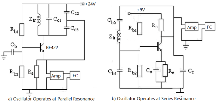
Oscillator is a circuit or device that produces a periodic signal. It feeds back the output signal to the input through a feedback mechanism, and continuously strengthens the input signal until a stable oscillation is formed. The frequency stability and output waveform of the oscillator have important effects on its application range.
What is Ring Oscillator
Ring oscillator is an electronic circuit that is widely used in various fields, such as audio synthesis, clock circuits, digital television, etc. It can produce stable periodic oscillation signal, and the output frequency is accurate and reliable.
A ring oscillator is also a type of electronic oscillator that is commonly used in integrated circuit (IC) design. It consists of an odd number of inverters (also known as NOT gates) arranged in a direct-coupled, ring configuration.
Inverters play a critical role in the functioning of a ring oscillator. An inverter is a digital logic gate that reverses the logic state of its input. If the input is "1", the output will be "0" and vice versa.
The odd number of inverters ensures that there is no stable state for the signals within the ring. This means that a signal introduced into the ring will continue to propagate indefinitely. For example, if a "1" is introduced into the ring, it will pass through the inverters, flipping between "1" and "0", and continue to oscillate around the ring.
This continual oscillation generates a repeating pattern of highs ("1") and lows ("0"), creating a digital signal that can be used as a clock signal in digital circuits.
The frequency of this oscillation depends on the total delay through the ring, which is determined by the number of inverters and their individual propagation delays.
In summary, a ring oscillator is a simple and effective circuit that leverages the properties of inverters to produce a continuous, oscillating signal.

Figure 1: ring oscillator circuit diagram
Working principle of Ring Oscillator
The ring oscillator is made by connecting an odd number of inverters from end to end using the inherent transmission delay time of the gate circuit, which has no steady state. Because at static (assuming no oscillation), the input and output of any inverter can not be stable at a high level or a low level, and can only be between high and low levels, in an amplified state.
Suppose that v11 has a small positive jump for some reason, after the transmission delay time tpd of G1, v12 has a larger negative jump, after the transmission delay time tpd of G2, v13 has a larger positive jump, after the transmission delay time tpd of G3, A larger negative jump is generated in vo and fed back to the G1 input. It can be seen that after 3tpd, v11 will automatically jump to a low level, and after 3tpd, v11 will jump to a high level. This cycle is repeated, resulting in self-excited oscillations. As shown in Figure 2, it can be seen that the oscillation period is T=6tpd
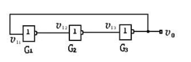
Figure 2: The principle circuit of a ring oscillator

Figure 3: Operating waveform of a ring oscillator
Ring oscillator frequency formula
The frequency of a ring oscillator is determined by the total delay time of the signal traveling through all the inverters in the loop. If 'N' is the number of stages (inverters) in the ring oscillator and 'T' is the delay time for each stage, the oscillation frequency (f) can be calculated using the following formula:
f = 1 / (2*N*T)
This formula states that the frequency is equal to one divided by twice the product of the number of stages and the delay time per stage. The factor of 2 appears because a complete cycle of oscillation includes both a high interval and a low interval, and each of these intervals is equal to 'N*T'.
It's important to note that in a practical scenario, the delay 'T' for each stage can be affected by various factors such as process variations, temperature, voltage, and loading conditions. Therefore, in a real-world application, the frequency of a ring oscillator may show some variations.
Ring Oscillator Design
**1. Number of Stages:**
A ring oscillator is composed of an odd number of stages, each of which is typically a NOT gate or inverter. The odd number of stages ensures that the circuit is unstable and will oscillate.
**2. Type of Gates:**
In most cases, inverters are used as the basic building block for ring oscillators. This is because inverters are simple, readily available in most technology libraries, and their behavior is well understood.
**3. Propagation Delay:**
The total propagation delay of the circuit determines the frequency of oscillation. Each inverter contributes to the total delay, so the choice and design of the inverters can significantly impact the performance of the oscillator.
**4. Power Supply and Load:**
The power supply voltage and the load on the oscillator can also affect its performance. These factors need to be considered in the design process.
**5. Layout:**
In a physical implementation, the layout of the ring oscillator on the chip can also impact its performance due to factors like parasitic capacitance and resistance.
**6. Technology:**
The specific technology used to implement the ring oscillator (e.g., CMOS, BiCMOS, GaAs, TTL and SOI) can also impact its performance and characteristics. Designing a ring oscillator with CMOS technology provides the benefits of low power consumption and high noise immunity, making it ideal for many applications in digital IC design. In the following, we will discusse how to design a ring oscillator using CMOS technology.
Ring Oscillator Design using CMOS
- **Inverter Design**: The basic unit of a ring oscillator is the inverter, which consists of a PMOS (p-type metal-oxide-semiconductor) transistor and an NMOS (n-type metal-oxide-semiconductor) transistor in a CMOS technology. The NMOS transistor pulls the output low when the input is high, and the PMOS transistor pulls the output high when the input is low, creating the inversion function.
- **Choosing the Number of Stages**: A ring oscillator requires an odd number of inverter stages to ensure oscillation. Each stage will invert the signal it receives, and with an odd number of stages, the feedback will always contradict the original input, causing continuous oscillation.
- **Connecting the Stages**: The output of each inverter is connected to the input of the next, forming a ring. The output of the last inverter is fed back into the input of the first.
- **Propagation Delay**: The oscillation frequency depends on the total propagation delay through all the inverters in the ring. In CMOS technology, this delay depends on factors like transistor sizes, load capacitance, and supply voltage.
- **Simulation and Testing**: After the design is complete, it's important to simulate and test the ring oscillator to verify the oscillation frequency and other performance characteristics.
- **Implementation**: Finally, the design can be fabricated using CMOS technology. Care must be taken in the layout to reduce parasitic capacitance and ensure consistent performance across all stages.
Ring Oscillator applications
1, clock signal source: the oscillator can produce stable periodic signals for applications such as clock signal sources.
2, frequency source: the oscillator can produce accurate fixed frequency signals for applications such as frequency sources.
3, signal generator: oscillator can produce a variety of complex waveform signals, used in signal generators and other applications.
4, modulator: oscillator can be used to generate modulated signals, such as AM, FM, PM and other modulated signals.
5, power supply: the oscillator can be used to generate DC power, AC power and other applications.
Ring Oscillator features
-The oscillation frequency is stable, which is suitable for occasions requiring high precision;
-Pure waveform, low harmonic content;
-The output power is low, and it is suitable for circuits with high drive sensitivity.
Ring Oscillator advantages and disadvantages
Advantages:
-
Simplicity: Ring oscillators are relatively simple to design and implement, involving only a series of inverters connected in a loop.
-
No External Components: They don't require any external components like resistors, capacitors or inductors, which simplifies the design and reduces cost.
-
Integration: They are easy to integrate into larger digital integrated circuits.
-
Testability: Ring oscillators are useful for testing and characterizing digital logic technologies and semiconductor fabrication processes.
-
Tunability: The frequency of oscillation can be adjusted by changing the number of stages or the supply voltage.
Disadvantages
-
Stability: The frequency output is highly dependent on environmental conditions (like temperature and voltage), and on manufacturing process variations.
-
Efficiency: They are not as power-efficient as some other types of oscillators, leading to static power dissipation.
-
Noise Susceptibility: They can be susceptible to noise, which may cause frequency instability or jitter.
-
Start-Up Time: They may have a longer start-up time compared to other types of oscillators.
-
Frequency Control: There's a lack of fine control over the output frequency compared to other oscillator types.