Resistors are fundamental electronic components that are commonly utilized to regulate the flow of electrical current in electrical circuits. They are intended to impede the passage of electricity and so control the amount of current that flows through a circuit. This current management is critical in a wide range of electrical applications, from basic circuits to more complicated systems. After understanding the definition of resistor, we need to know that how resistor works ?A resistor works by creating resistance to limit the flow of current in a circuit, and converting some of the electrical energy into heat. The main purpose of a resistor is to control the flow of current in a circuit, divide voltage, set the correct working conditions for other components, and generate heat in certain applications.
Understanding how to utilize resistors and apply Ohm's law is a fundamental part of electrical engineering and is required for anybody interested in building and designing electrical circuits. We will look at the fundamentals of resistors and how to apply Ohm's law to calculate resistance, current, and voltage in electrical circuits.
1. Introduction to Resistors:
Definition and Types of Resistors
A resistor is a type of electrical component that opposes the passage of electricity. It is used to change the voltage and current levels to match the unique needs of an electrical system. It is meant to control the flow of current in a circuit.
There are several types of resistors , each having their own distinct properties and purposes. Some examples of typical resistors are:
Fixed Resistors: These are the most common form of resistor and have a set resistance value. They come in a variety of resistance levels, tolerances, and power ratings.
Variable Resistors: These resistors feature adjustable resistance, providing for more control over the flow of current in a circuit.
Wirewound Resistors: Winding a wire, such as nichrome, around a ceramic or metal core creates these resistors. They are made to withstand high power levels and are widely used in power supply and other high-power applications.
Carbon Film Resistors: A tiny coating of carbon is deposited onto a ceramic or plastic rod to create these resistors. They are reasonably priced and commonly utilized in low-power applications.
Metal Film Resistors: These resistors are similar to carbon-film -and-metal-film-resistors>carbon film resistors in that they generate resistance using a metal film rather than carbon. They outperform carbon film resistors in terms of stability and accuracy.
Each type of resistor has distinct benefits and disadvantages, and the resistor selected will be determined by the exact needs of the circuit.
How to Identify Resistors in an Electrical Circuit
There are several ways to identify resistors in an electrical circuit:
Color Code: Many fixed resistors feature color-coded bands that show the resistance value. The first and second bands represent the first two digits of the resistance value, the third the multiplier, and the fourth the tolerance.

Size and Shape: Some resistors come in a variety of forms and sizes, which might aid in their identification. Wirewound resistors, for example, are frequently cylindrical and bigger than other forms of resistors.
Component Marking: Some resistors are labeled with their resistance value or a component number, which may be used to identify them.
Circuit Diagrams: Electrical circuit diagrams depict the components and their connections, which makes identifying resistors in a circuit easier.
It is critical to accurately identify resistors in an electrical circuit, as using the incorrect resistor might cause the circuit to fail or possibly cause damage to the components.
2. Understanding Resistance:
Explanation of Resistance in Electrical Circuits
In an electrical circuit, resistance is a measure of the resistance to the passage of electric current. It is a material property that opposes the flow of electric charge. The Ohm (Ω) is the unit of resistance.
Resistance in a circuit can be caused by the resistance of the wire material, the resistance of the components in the circuit, and the resistance of the connections between the components. A material's resistance is determined by its composition and temperature. Those that conduct electricity well have low resistance, while materials that conduct poorly have high resistance.
A circuit's resistance impacts current flow by turning electrical energy into heat, which is lost energy. The amount of resistance in a circuit has a direct impact on the quantity of current that flows through it. According to Ohm's law, current in a circuit is directly proportional to voltage applied and inversely proportional to resistance. This means that increasing the voltage causes the current to increase, while increasing the resistance causes the current to decrease.
Resistance may also influence voltage in a circuit. When a circuit has a high resistance, the voltage drops significantly, lowering the potential energy available to accomplish work.
The Unit of Measurement for Resistance (Ohms)
An Ohm is the amount of resistance in a circuit that allows one ampere of current to pass through it when one volt is placed across it. In other words, 1 Ohm of resistance results in a 1 volt voltage drop when a current of 1 ampere flows through the circuit.
Ohm's law describes the relationship between voltage, current, and resistance, stating that the current flowing through a circuit is directly proportional to the voltage put across it and inversely proportional to the resistance of the circuit.
Ohm's law is a basic connection in electrical engineering that is commonly used to predict electrical circuit performance. By knowing the voltage and resistance of a circuit , you can determine the current flowing through it, and vice versa. This connection enables the construction and analysis of a broad range of electrical circuits, from simple resistive circuits to complicated electronic systems.
How to Measure Resistance Using A Multimeter
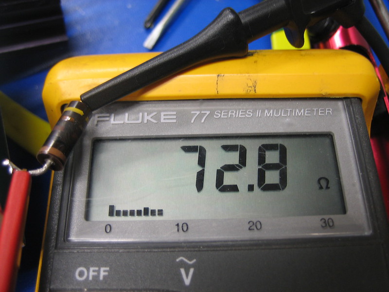
It is straightforward to measure resistance with a multimeter. Here are the actions to take:
Set the multimeter to the resistance (Ω) measurement range: To choose the measurement range, most multimeters contain a dial or switch. The resistance range is often symbolized by the Greek letter Omega () or the resistance symbol .
Turn off the power to the circuit: Before measuring the resistance, make sure all power sources in the circuit are turned off. This is done to avoid electric shock and assure precise readings.
Connect the multimeter probes to the circuit: Connect the multimeter probes to the two spots in the circuit where you wish to measure the resistance. Check that the probes are attached to the right places and have excellent contact with the circuit.
Read the resistance: The resistance value will be shown on the screen of the multimeter. Because the value should be steady, you may need to wait a few seconds for it to settle.
Repeat the measurement if necessary: If you're measuring resistance in a circuit with numerous components, you might have to repeat the measurement a few times to acquire a reading for each one.
It's vital to remember that some components, like diodes and transistors, might have a non-linear connection between voltage and current, which means their resistance may not be constant. In these circumstances, specialist procedures and equipment are required to precisely measure the resistance.
Also, bear in mind that resistance measurements are impacted by temperature, so if you need to make reliable comparisons between multiple readings, test the resistance at a consistent temperature.
3. Applying Ohm's Law:
Definition and Equation of Ohm's Law
Ohm's Law outlines the relationship between the current flowing through a circuit, the voltage across the circuit, and the resistance of the circuit. The rule is named after the German scientist Georg Simon Ohm, who initially proposed it in 1827.
The equation for Ohm's Law is given by:
V = IR
where V is the voltage across the circuit in volts (V), I is the current flowing through the circuit in amperes (A), and R is the resistance of the circuit in ohms (Ω).
According to Ohm's Law, the current flowing through a circuit is directly proportional to the voltage put across it and inversely proportional to the circuit's resistance. In other words, increasing the voltage across a circuit increases the current passing through it, whereas increasing the resistance of the circuit decreases the current flowing through it.
Ohm's Law is a valuable tool for evaluating and constructing electrical circuits because it gives a basic and straightforward approach to explain circuit behavior in terms of the fundamental characteristics of voltage, current, and resistance. Knowing the voltage and resistance of a circuit allows you to determine the current flowing through it, and vice versa, allowing you to create and evaluate a wide range of electrical circuits.
How to Use Ohm's Law to Calculate Current, Voltage, and Resistance in A Circuit
Given two of the three factors, Ohm's Law may be used to compute current, voltage, and resistance in a circuit. Ohm's Law is denoted by the equation:
V = IR
where V denotes the voltage across the circuit in volts (V), I denotes the current flowing through the circuit in amperes (A), and R is the circuit resistance in ohms ().
Here are the procedures for calculating each parameter using Ohm's Law:
Current (I) calculation: The current may be computed using the following formula given the voltage (V) and resistance (R):
I = V/R
Calculating voltage (V): Given the current (I) and resistance (R), the voltage can be calculated using the following formula:
V = IR
Calculating resistance (R): Given the voltage (V) and current (I), the resistance can be calculated using the following formula:
R = V/I
It's vital to remember that Ohm's Law only applies to linear circuits, which have a straight line relationship between voltage, current, and resistance. The connection between these factors is more complex in non-linear circuits, and Ohm's Law may not be relevant. In many circumstances, however, even non-linear circuits may be described as a succession of linear parts, and Ohm's Law can still be used to study the circuit's behavior.
Examples of Applying Ohm's Law in Electrical Circuits
Here are some instances of how Ohm's Law may be used in electrical circuits to compute current, voltage, and resistance:
Calculating the current in a circuit: Assume a 12 volt power is supplied over a 4 ohm resistance circuit. We may compute the current passing through the circuit using Ohm's Law as follows:
I = V/R = 12V / 4Ω = 3A
Calculating the voltage in a circuit: Assume a 0.5 ampere current is flowing over a 10 ohm resistance circuit. We may determine the voltage across the circuit using Ohm's Law as follows:
V = IR = 0.5A * 10Ω = 5V
Using a circuit to calculate resistance: Assume a 120-volt voltage is put across a circuit with a current of 0.6 amps flowing across it. Using Ohm's Law, we can compute the circuit's resistance as follows:
R = V/I = 120V / 0.6A = 200Ω
These are only a few instances of how Ohm's Law may be used in electrical circuits to compute current, voltage, and resistance. This equation may be used to evaluate and comprehend the behavior of a wide range of electrical circuits, from simple resistive circuits to more sophisticated circuits with numerous components.
4. Controlling Current and Voltage with Resistors:
Explanation of How Resistors Can Be Used To Control Current and Voltage in a Circuit
Resistors are passive electrical components that are often employed in circuits to regulate current and voltage. They do this by putting resistance into the circuit, which limits current flow and lowers voltage.
Resistors are commonly used to limit the amount of current flowing through a circuit. This is especially crucial when connecting sensitive components to a power source, such as microcontrollers or other electronics. By connecting a resistor in series with the component, you may restrict the amount of current flowing through it and protect the electronics.
Resistors can also be used to regulate the voltage of a circuit. This is frequently accomplished by employing a voltage divider circuit, which consists of a series of resistors coupled in such a way as to minimize the voltage across the load. A voltage divider, for example, can be used to lower the voltage from a battery or other power source to a level acceptable for a certain component.
Furthermore, resistors can be utilized in a circuit to shape the voltage waveform. Resistors, for example, can be employed in RC (resistor-capacitor) circuits to filter signals, decrease noise, and alter the frequency response.
It is possible to dissipate excess power as heat by connecting a resistor in line with the load, which is useful in cases where overheating might harm the electronics or constitute a safety problem.
Steps To Connect Resistors in Series and Parallel in a Circuit
Connecting resistors in series or parallel in a circuit can significantly affect the total resistance of the circuit and, as a result, the flow of current and voltage in the circuit. To link resistors in series and parallel in a circuit, follow these steps:
Connecting resistors in series:

- Take two or more resistors.
- Connect the first resistor to the power source.
- Connect the second resistor to the first resistor.
- Repeat the process of connecting resistors end-to-end until all resistors are connected in a chain.
- Connect the final resistor to the load.
Connecting resistors in parallel:

- Take two or more resistors.
- Connect one end of the first resistor to the power source.
- Connect the other end of the first resistor to one end of the second resistor.
- Repeat the process of connecting resistors to the common point until all resistors are connected.
- Connect the other end of the final resistor to the load.
When resistors are linked in series, the overall resistance of the circuit is equal to the sum of the individual resistors. When resistors are linked in parallel, the overall resistance of the circuit is less than the resistance of the smallest resistor in the circuit.
By connecting resistors in series or parallel in various combinations, circuits with a broad variety of resistance values may be created, which can be used to regulate the flow of current and voltage in the circuit.
As a crucial component in an electric circuit. Resistors have some uses:
-
Current Control: Resistors are used to limit the amount of current flowing in a circuit. This can be crucial for protecting sensitive components that might be damaged by high currents.
-
Voltage Division: In a series circuit, resistors can be used to create a voltage drop and divide the voltage. This is useful in applications where different components require different voltages.
-
Biasing: Resistors are used to set up proper working conditions for active devices like transistors.
-
Heat Generation: In some devices like heaters and incandescent light bulbs, resistors convert electrical energy into heat.
-
Feedback: In operational amplifiers, resistors are used in the feedback loop to control the gain of the amplifier.
-
Load: Resistors can be used as 'loads' in a circuit, where they convert electrical energy to other forms of energy, like light or heat.
Remember, the specific use of a resistor in a circuit will depend on the design and purpose of that circuit.
How to Calculate Total Resistance in Series and Parallel Circuits
Using Ohm's Law and the connection between resistance, current, and voltage, the total resistance of a circuit may be computed. The total resistance of a circuit with resistors linked in series or parallel may be computed as follows:
Resistors in series:
The total resistance in a series circuit is equal to the sum of the individual resistances:
R_total = R1 R2 R3 ... Rn
where R1, R2, R3, ..., Rn are the resistance values of the individual resistors in the circuit.
Resistors in parallel:
The total resistance in a parallel circuit can be calculated using the reciprocal of the sum of the reciprocals of the individual resistances:
1/R_total = 1/R1 1/R2 1/R3 ... 1/Rn
where R1, R2, R3, ..., Rn are the resistance values of the individual resistors in the circuit.
It's vital to remember that the total resistance in a circuit is determined by how the resistors are linked, therefore understanding the difference between series and parallel circuits is essential for properly calculating total resistance.
Conclusion
Finally, electrical resistance is an essential topic in electrical circuits because it influences the passage of current and voltage. Ohm's Law is a basic relationship between resistance, current, and voltage that may be used to compute these quantities in a circuit. By connecting resistors in series or parallel in various combinations, circuits with a broad variety of resistance values may be created, which can be used to regulate the flow of current and voltage in the circuit. Understanding the fundamental principles of resistance and Ohm's Law is critical for planning, constructing, and debugging electrical circuits.
If you would like to search for more articles on this site for any topic, see our search engine. You can search the whole website for any information you may need.